


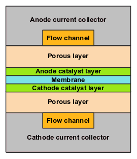
The electrolysis and hydrogen (H2) pump model allows you to model polymer electrolyte membrane (PEM), hydrogen pump, and alkaline electrolysis devices [348]. Both PEM electrolysis and alkaline electrolysis produce gaseous hydrogen and oxygen from liquid water, while the hydrogen pump is used to purify and compress hydrogen through an electrochemistry process. With the electrolysis and H2 pump model, both active catalyst layers and ionic conducting electrolyte (also known as the membrane in electrolysis terminology) are included in the computational domain. To determine the physical domains that are included in the electrolysis and H2 pump model, a schematic of typically electrolysis device is shown in Figure 18.2: Schematic of an Electrolysis Device.
In the electrolysis and H2 pump model in Ansys Fluent, two electric potential fields are solved in the following zones:
in the electrolyte zone and the catalyst layers
in the catalyst layers, the porous electrode, and the current collectors
The flow field is only solved in the flow channels, porous electrodes, and catalyst layers. In the membrane, the flow field is not resolved since the membrane is used to separate the anode and cathode sides.
The rates of electrochemical reactions are computed in the catalyst layers at both the anode and the cathode. The current density value is estimated based on the cell voltage, which can be either directly specified or computed from a specified average current density.
The electrolysis devices differ in electrochemical reactions in catalyst layers:
For PEM electrolysis, the electrochemical reactions are:
For alkaline electrolysis, the electrochemical reactions are:
For the hydrogen pump, the electrochemical reactions are:


Although electrochemistry reactions often involve ionic species, the electrolysis and H2 pump model in Ansys Fluent does not track them to simplify modeling. That is, only the transport equations of neutral species are solved.
In Ansys Fluent, the following approaches are used for modeling the membrane electrode assemblies (MEA) zones (the catalyst layers and the membrane):
Resolved
In this approach, the MEA zones are included in the computational domain, and the dual potential equations are solved. For details, see Resolved Modeling Approach.
Unresolved 0D
In this approach, the MEA zones are not included in the computational domain. Instead, they are modeled as a pair of wall and wall-shadow faces called “electrolyte interfaces". The species sources, energy sources and the sinks due to the electrochemical reactions are added to the adjacent computational cells. Because only one potential equation is solved, the computational cost is reduced. For details, see Unresolved 0D Modeling Approach
Note: The resolved approach can be used only for unit electrolysis cell modeling, while the unresolved 0D approach can be used for modeling both unit electrolysis cells and electrolysis stacks.