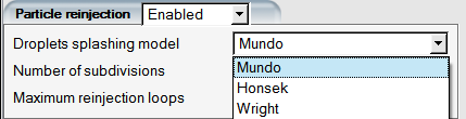
Crystals that impinge on cold surfaces of the aircraft will bounce and may collide with downstream components, such as air data probes, or be ingested by the engine. Similarly, supercooled large droplets (SLDs) can splash and bounce and partially or completely re-enter the flow stream as ejecta. To calculate possible reimpingement due to such events, the Particle reinjection option can be enabled. This option first executes a standard DROP3D run and the solution is saved as the primary solution. Next, reinjection calculations track the particles (droplets or crystals) that rejoin the airflow from the primary impact points. Particles may bounce multiple times before finally sticking to a wall or leaving the computational domain. Final DROP3D solution file, droplet or crystal, contains a combination of the primary and all reinjection solutions.
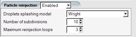
For reinjection calculations, wall boundaries where particles are re-emitted are temporarily converted to inlets. The boundary conditions for velocity, concentration, and droplet size are determined using crystals bouncing models for crystals and post-processing models for SLDs. Number of subdivisions setting splits the collective reinjecting wall facets into separate inflow boundaries, to individually track secondary particle flow for each. Splitting the secondary flow analysis helps prevent coalescence of Eulerian particle tracks and increases the fidelity of the simulation. In case of SLDs, all wall boundaries will be included in reinjection analysis. For crystal reinjection, the user has to activate which walls to reinject from. Only cold walls should be enabled for crystal reinjection where it is guaranteed that no crystals can stick due to wall heating or possible water runback.
A stream of particles may bounce off a series of surfaces, requiring an iterative approach to compute new impingement areas and calculate subsequent reinjection streams. Once all subdivisions are analyzed, the next reinjection loop begins. The maximum reinjection loops is a user input. When total reinjecting mass falls below 1% of primary water catch, the reinjection iterations will stop automatically.
The primary droplet and crystal solutions are saved in droplet.primary and crystal.primary files in the simulation directory. In the reinjection phase of the calculations, the results from subdivisions are merged into a composite file one by one after completion and saved to the disk with the standard names of crystal and droplet. These composite files are the final output of the simulation which are meant to be used with ICE3D or CHT3D for icing and IPS analyses. The execution can be stopped using the button on the GUI panel, and the composite file will contain the data from the latest completed subdivision at the current reinjection iteration. At this time, restarting the simulation from this file to continue the reinjection process is not possible, but will be added in later releases.
Crystal sticking and collection on surfaces is a function of their melt fraction and the water film coverage of the surface they are impinging on. In a standalone DROP3D calculation the surface film distribution is not available and it is not possible to properly decide if crystals can stick or not. In external reinjection simulations, crystals are set to fully bounce on reinjection-enabled walls. Therefore, crystal reinjection should be limited to wall boundaries that are not heated and have no possibility of having runback water. By default, all walls are disabled for particle reinjection and the user enables select walls to initiate the reinjection calculation. This is a safety measure not to bounce all crystals off all surfaces where some might have the potential of sticking due to heating or water film coverage as will be determined by ICE3D.
Cases where crystal reinjection may apply are, for example, crystals bouncing off the aircraft radome and entering air data probes, or crystals bouncing off the unheated parts of the wing and enriching the ICC ingested by aft-mounted engines.
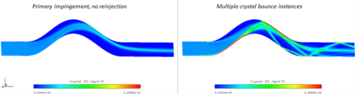
Figure 5.15: Crystal Reinjection Inside a Channel. Primary Impingement Result (Left), Composite Solution Combining Primary and Subdivision Calculations (Right).
SLDs can splash and bounce off the aircraft and impinge further downstream where surfaces are usually not protected for icing. The physics of the splashing and bouncing does not involve thermodynamic effects and phase change and it is recommended to enable reinjection on all primary impingement surfaces. Grouping wall boundaries of leading edges, nacelles, etc. can help reduce the total number of subdivisions that will have to be solved during a reinjection iteration. The reinjection boundary conditions for SLDs are determined using the SLD-by-post-processing models: