VMFRT001
VMFRT001
Large Eddy Simulation in Internal Combustion Engine Case
Overview
| Reference | Thobois, L., Rymer, G., Soulères, T., and Poinsot, T., "Large-Eddy Simulation in IC Engine Geometries, SAE Paper 2004-01-1854," SAE Technical Paper Series, 2004-01-1854, 2004. |
| Solver | Ansys Forte |
| Physics/Models | Non-reacting flow, gas-phase only |
| Input Files |
VM_LES_initialization.ftsim
|
| Project Files | Link to Project Files Download Page |
Test Case
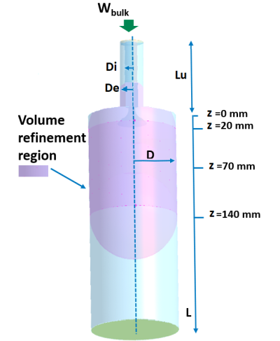
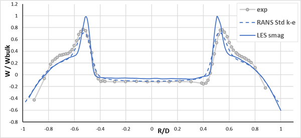
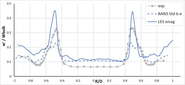
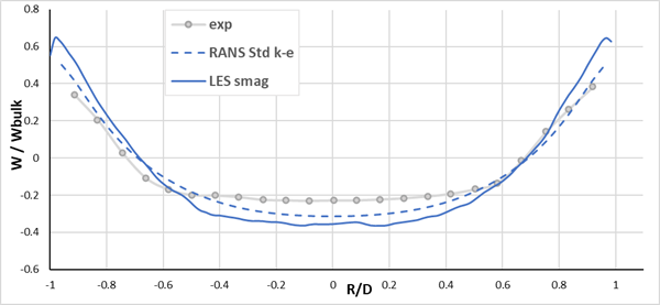
This test case simulates a simplified IC engine geometry with a nonreacting steady-state flow. See Figure 199: Sketch of the geometry with the static volume refinement region. The valve is fixed in the open position and has a seat of 4 mm, the expansion ratio is 3.5 and there is no swirl. A static volume refinement is present around the jet region to better capture the recirculation, while Solution Adaptive Mesh refinements (SAM) are activated based on the velocity gradient (see the table below for details). The turbulence model settings are the default for all parameters for both LES and Standard k-ϵ while the LES simulation is initialized using the RANS solution. The resulting velocity profiles and their fluctuations in Figure 200: Normalized axial velocity at z = 20 mm, Figure 201: Normalized axial velocity fluctuation at z = 20 mm, and Figure 202: Normalized axial velocity at z = 70 mm are compared to the laser doppler anemometry experimental measurements (Thobois 2004).


