


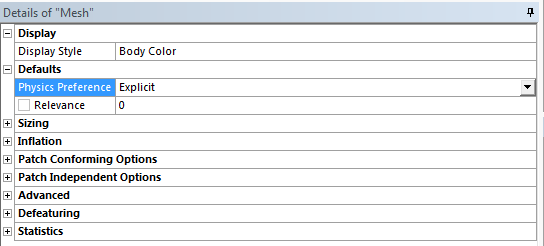
Before running the simulation, the meshing has to be thoroughly checked to ensure all requirements are met. The Explicit and Implicit solvers require different types of meshes. The simplest way to differentiate is to switch the Physics Preference option between Explicit and Mechanical. However, if the Model cell connection is used, the models are going to make use of the same mesh; this might mean that when the mesh is made to work with the Explicit solver it might not solve anymore with the Implicit solver. Generally, with a complex geometry we do not want to use the same mesh for both solvers.
The Implicit solver works well when the areas of interest have much denser meshes. This is not the case for the Explicit solver. First, the time step (the time increment at which the Explicit solver advances) is controlled by the smallest mesh element - thus the size of the smallest elements in the interest area will control the solve for the whole model, increasing the run times. Second, the nature of the Explicit Dynamics solver is such that it works best with cuboid, evenly distributed mesh elements throughout the model. Lastly, this element size difference will skew the results much more than with the Implicit solver, because of the use of each individual element mass, deformation, and velocity for the calculations.
To ensure a good Explicit solve, you need to look at the mesh maximum and minimum element size in the mesh statistics. The smaller the spread of element sizes, the better.
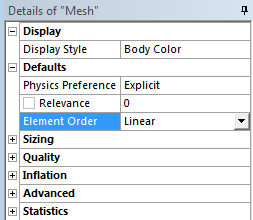
The implicit solver can create midside nodes in the elements to aid the accuracy of the solution. This is not possible with the Explicit solver. If you want to use the same mesh for both solvers, set Element Order to Linear in the Defaults section of the Mesh settings. If this is not set, the error Higher order elements detected. Element Order must be Linear for Explicit Dynamics analyses. will be generated.
Note: It is important when there are regions of the geometry which are relatively thin and will encounter bending, that they are meshed with at least two mesh elements across their thickness to ensure the Explicit solver models the bending correctly. Because of this, you may want to use shell bodies where more appropriate; the two elements across recommendation can lead to a very small time step overall.
Even though more complex geometry is quite difficult to mesh with hex elements, they are the most suitable type for the simulation. If you are familiar with the Implicit solver, you should understand the various ways to control how the mesher approaches the geometry. The geometry should be swept meshed wherever possible. Shell bodies should be face meshed to ensure only rectangular elements are used.