


Included in this section:
EnSight5 Wild Card Name Specification
EnSight5 Measured/Particle File Format
Note: The EnSight6 format replaces and includes all aspects of the older EnSight5 format. This description is included for completeness but use of the EnSight6 format with EnSight 6.x and later versions is encouraged!
EnSight5 data consists of the following files:
Geometry (required)
Results (optional) (points to other variable files and possibly to changing geometry files)
Measured (optional) (points to measured geometry and variable files)
The results file contains information concerning scalar and vector variables. EnSight makes no assumptions regarding the physical significance of the scalar and vector variables. These files can be from any discipline. For example, the scalar file can include such things as pressure, temperature, and stress. The vector file can be velocity, displacement, or any other vector data.
All variable results for EnSight5 are contained in disk files - one variable per file. Additionally, if there are multiple time steps, there must be a set of disk files for each time step.
Sources of EnSight5 data include the following:
Data that can be translated to conform to the EnSight5 data format
Data that originates from one of the translators supplied with the EnSight application
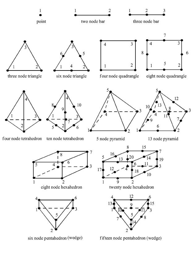
The EnSight5 format supports a defined element set as shown below. The data must be defined in this element set. Elements that do not conform to this set must either be subdivided or discarded.
The elements that are supported by the EnSight5 format are:
The EnSight5 format consists of keywords followed by information. The following items are important to remember when working with EnSight5 geometry files:
You do not have to assign node IDs. If you do, the element connectivities are based on the node numbers. If you let EnSight assign the node IDs, the nodes are considered to be sequential starting at node 1, and element connectivity is done accordingly. If node IDs are set to off, they are numbered internally; however, you will not be able to display or query on them. If you have node IDs in your data, you can have EnSight ignore them by specifying "node id ignore." Using this option may reduce some of the memory taken up by the Client and Server, but remember that display and query on the nodes will not be available.
You do not need to specify element IDs. If you specify element IDs, or you let EnSight assign them, you can show them on the screen. If they are set to off, you will not be able to show or query on them. If you have element IDs in your data you can have EnSight ignore them by specifying "element id ignore." Using this option will reduce some of the memory taken up by the Client and Server. This may or may not be a significant amount, and remember that display and query on the elements will not be available.
The format of integers and real numbers must be followed (See the Geometry Example below).
Integers are written out using the following integer format:
From C:
8dformatFrom FORTRAN:
i8format
Real numbers are written out using the following floating-point format:
From C:
12.5eformatFrom FORTRAN:
e12.5format
The number of integers or reals per line must also be followed!
By default, a Part is processed to show the outside boundaries. This representation is loaded to the Client host system when the geometry file is read (unless other attributes have been set on the workstation, such as feature angle).
Coordinates must be defined before any Parts can be defined. The different elements can be defined in any order (that is, you can define a hexa8 before a bar2).
Generic Format
Not all of the lines included in the following generic example file are necessary:
description line 1
description line 2
node id <off/given/assign/ignore>
element id <off/given/assign/ignore>
coordinates
# of points
id x y z
id x y z
id x y z
.
.
.
part #
description line
point
number of points
id nd
id nd
id nd
.
.
.
bar2
number of bar2’s
id nd nd
id nd nd
id nd nd
.
.
.
bar3
number of bar3’s
id nd nd nd
id nd nd nd
id nd nd nd
.
.
.
tria3
number of three node triangles
id nd nd nd
id nd nd nd
id nd nd nd
.
.
.
tria6
number of six node triangles
id nd nd nd nd nd nd
.
.
.
quad4
number of quad 4’s
id nd nd nd nd
id nd nd nd nd
id nd nd nd nd
id nd nd nd nd
.
.
.
quad8
number of quad 8’s
id nd nd nd nd nd nd nd nd
id nd nd nd nd nd nd nd nd
id nd nd nd nd nd nd nd nd
id nd nd nd nd nd nd nd nd
.
tetra4
number of 4 node tetrahedrons
id nd nd nd nd
id nd nd nd nd
id nd nd nd nd
id nd nd nd nd
.
.
.
tetra10
number of 10 node tetrahedrons
id nd nd nd nd nd nd nd nd nd nd
id nd nd nd nd nd nd nd nd nd nd
id nd nd nd nd nd nd nd nd nd nd
id nd nd nd nd nd nd nd nd nd nd
.
.
.
pyramid5
number of 5 node pyramids
id nd nd nd nd nd
id nd nd nd nd nd
id nd nd nd nd nd
id nd nd nd nd nd
.
.
.
pyramid13
number of 13 node pyramids
id nd nd nd nd nd nd nd nd nd nd nd nd nd
id nd nd nd nd nd nd nd nd nd nd nd nd nd
id nd nd nd nd nd nd nd nd nd nd nd nd nd
id nd nd nd nd nd nd nd nd nd nd nd nd nd
.
.
.
hexa8
number of 8 node hexahedrons
id nd nd nd nd nd nd nd nd
id nd nd nd nd nd nd nd nd
id nd nd nd nd nd nd nd nd
id nd nd nd nd nd nd nd nd
.
.
.
hexa20
number of 20 node hexahedrons
id nd nd nd nd nd nd nd nd nd nd nd nd nd nd nd nd nd nd nd nd
id nd nd nd nd nd nd nd nd nd nd nd nd nd nd nd nd nd nd nd nd
id nd nd nd nd nd nd nd nd nd nd nd nd nd nd nd nd nd nd nd nd
id nd nd nd nd nd nd nd nd nd nd nd nd nd nd nd nd nd nd nd nd
id nd nd nd nd nd nd nd nd nd nd nd nd nd nd nd nd nd nd nd nd
.
.
.
penta6
number of 6 node pentahedrons
id nd nd nd nd nd nd
id nd nd nd nd nd nd
id nd nd nd nd nd nd
id nd nd nd nd nd nd
id nd nd nd nd nd nd
.
.
.
penta15
number of 15 node pentahedrons
id nd nd nd nd nd nd nd nd nd nd nd nd nd nd nd
id nd nd nd nd nd nd nd nd nd nd nd nd nd nd nd
id nd nd nd nd nd nd nd nd nd nd nd nd nd nd nd
id nd nd nd nd nd nd nd nd nd nd nd nd nd nd nd
id nd nd nd nd nd nd nd nd nd nd nd nd nd nd nd
.
.
.
.
EnSight5 Geometry Example
The following is an example of an EnSight geometry file:
this is an example problem
this is the second description line
node id given
element id given
coordinates
10
5    1.00000e+00 0.00000e+00 0.00000e+00
100  0.00000e+00 1.00000e+00 0.00000e+00
200  0.00000e+00 0.00000e+00 1.00000e+00
40   1.00000e+00 1.00000e+00 0.00000e+00
22   1.00000e+00 0.00000e+00 1.00000e+00
1000 2.00000e+00 0.00000e+00 0.00000e+00
55   0.00000e+00 2.00000e+00 0.00000e+00
44   0.00000e+00 0.00000e+00 2.00000e+00
202  2.00000e+00 2.00000e+00 0.00000e+00
101  2.00000e+00 0.00000e+00 2.00000e+00
part 1
This is Part 1, a pretty strange Part
tria3
    2
    101 100 200 40
    201 101 5 1000
tetra4
    1
    102 100 202 101 1000
part 2
This is Part 2, it is pretty strange also
bar2
    1
    103 101 1000
The Result file is an ASCII free format file that contains variable and time step information that pertains to a Particular geometry file. The following information is included in this file:
Number of scalar variables
Number of vector variables
Number of time steps
Starting file number extension and skip-by value
Flag that specifies whether there is changing geometry
Names of the files that contain the values of scalar and vector variables
The names of the geometry files that will be used for the changing geometry.
The format of the EnSight5 result file is as follows:
Line 1
Contains the number of scalar variables, the number of vector variables and a geometry-changing flag. (If the geometry-changing flag is 0, the geometry of the model does not change over time. If it is 1, then there is connectivity changing geometry. If it is 2, then there is coordinate only changing geometry.)
Line 2
Indicates the number of time steps that are available.
Line 3
Lists the time that is associated with each time step. There must be the same number of values as are indicated in Line 2. This "line" can actually span several lines in the file. You do not have to have one very long line.
Line 4
Specified only if more than one time step is indicated in Line 2. The two values on this line indicate the file extension value for the first time step and the offset between files. If the values on this line are 0 5, the first time step available has a subscript of 0, the second time step available has a subscript of 5, the third time step has a subscript of 10, and so on.
Line 5
Contains the names of the geometry files that will be used for changing geometry. This line exists only if the flag on Line 1 is set to 1 or 2. The geometry file name must follow the EnSight5 wild card specification.
Line 6 through Line [5+N] where N is the number of scalar variables specified in Line 1.
List BOTH the file names AND variable description that correspond to each scalar variable. There must be a file name for each scalar variable that is specified in Line 1.
If there is more than one time step, the file name must follow the EnSight5 wild card specification. See Note below.
Lines that follow the scalar variable files.
List the file names that correspond to each vector variable. There must be a file name for each vector variable that is specified in Line 1. If there is more than one time step, the file name must follow the EnSight5 wild card specification. See note below.
Note: Variable descriptions have the following restrictions:
The maximum variable name length is documented at the beginning of this chapter.
Duplicate variable descriptions are not allowed.
Leading and trailing white space will be eliminated.
Variable descriptions must not start with a numeric digit.
Variable descriptions must not contain any of the following reserved:
( [ + @ ! * $
) ] - space # ^ /
The generic format of a result file is as follows:
#_of_scalars #_of_vectors geom_chang_flag
#_of_timesteps
time1 time2 time3 .....
start_file_# skip_by_value
geometry_file_name.geo**
scalar0_file_name** description (19 max)
scalar1_file_name** description
.
.
.
vector0_file_name** description (19 max)
vector1_file_name** description
.
EnSight5 Result File Example 1
The following example illustrates a result file specified for a non-changing geometry file with only one time step:
2 1 0
1
0.0
exone.scl0 pressure
exone.scl1 temperature
exone.dis0 velocity
EnSight5 Result File Example 2
This example illustrates a result file that specifies a connectivity changing geometry that has multiple time steps.
1 2 1
4
1.0 2.0 2.5 5.0
0 1
extwo.geom**
pres.scl** pressure
vel.dis** velocity
grad.dis** gradient
The following files would be needed for example 2:
extwo.geom00 pres.scl00 vel.dis00 grad.dis00
extwo.geom01 pres.scl01 vel.dis01 grad.dis01
extwo.geom02 pres.scl02 vel.dis02 grad.dis02
extwo.geom03 pres.scl03 vel.dis03 grad.dis03
If multiple time steps are involved, the file names must conform to the EnSight5 wild-card specification. This specification is as follows:
File names must include numbers that are in ascending order from beginning to end.
Numbers in the files names must be zero filled if there is more than one significant digit.
Numbers can be anywhere in the file name.
When the file name is specified in the EnSight5 result file, you must replace the numbers in the file with an asterisk(*). The number of asterisks specified is the number of significant digits. The asterisk must occupy the same place as the numbers in the file names.
Variables files have one description line followed by a value for each node. For a scalar file there is one value per node, while for vector files there are three values per node.
The values must be written in the following floating point format ( 6 per line as shown in the examples below):
From C: 12.5e
format
From FORTRAN: e12.5
format
The format of a variables file is as follows:
Line 1
This line is a description line.
Line 2 through the end of the file contains the values at each node in the model. A generic example:
A description line
*.*****E+** *.*****E+** *.*****E+** *.*****E+** *.*****E+** *.*****E+**
*.*****E+** *.*****E+** *.*****E+** *.*****E+** *.*****E+** *.*****E+**
*.*****E+** *.*****E+** *.*****E+** *.*****E+** *.*****E+** *.*****E+**
EnSight5 Variable File Example 1
This example shows a scalar file for a geometry with seven defined nodes.
These are the pressure values for a 7 node geometry
1.00000E+00 2.00000E+00 3.00000E+00 4.00000E+00 5.00000E+00 6.00000E+00
7.00000E+00
EnSight5 Variable File Example 2
This example shows the vector file for a geometry with seven defined nodes.
These are the velocity values for a 7 node geometry
1.00000E+00 1.00000E+00 1.00000E+00 2.00000E+00 2.00000E+00 2.00000E+00
3.00000E+00 3.00000E+00 3.00000E+00 4.00000E+00 4.00000E+00 4.00000E+00
5.00000E+00 5.00000E+00 5.00000E+00 6.00000E+00 6.00000E+00 6.00000E+00
7.00000E+00 7.00000E+00 7.00000E+00
This file allows you to define Particle locations, sizes, etc. to display with the geometry. Typical uses are fuel droplets for combustion analysis or data derived from experiments on prototypes.
The measured/Particle files consist of the following:
Measured/Particle geometry file (referenced by the measured results file)
Measured/Particle results file (the filename, typically with a .mea suffix, which is put into the Data Reader's "(Set) Measured" field)
Measured/Particle variables file (referenced by the measured results file) which is the same format as an EnSight 5 variable file.
The format of the EnSight5 Measured/Particle geometry file is described below.
Note: There is only one description line and there must be an ID for each measured point.
The number of Particles can be different in each of the geometry file (if you have transient data), however, the number of values in each of the corresponding variable files must coincide, and the IDs of the Particles must be consistent in order to track the Particles at intermediate times or locations.
The format of an EnSight5 Measured/Particle geometry file is as follows:
Line 1
This line is a description line.
Line 2
Indicates that this file contains Particle coordinates. The words "particle coordinates" should be entered on this line without the quotes.
Line 3
Specifies the number of Particles.
Line 4 through the end of the file.
Each line contains the ID and the X, Y, and Z coordinates of each Particle. The format of this line is "integer real real real" written out in the following format:
From C: %8d%12.5e%12.5e%12.5e format
From FORTRAN: i8,
3e12.5 format
A generic measured/Particle geometry file is as follows:
A description line
particle coordinates
#_of_Particles
id xcoord ycoord zcoord
id xcoord ycoord zcoord
id xcoord ycoord zcoord
.
.
.
EnSight5 Measured Geometry/Particle File Example
The following illustrates an EnSight5 Measured Geometry/Particle file with seven
points:
This is a simple ensight5 measured geometry/particle file
particle coordinates
7
101 0.00000E+00 0.00000E+00 0.00000E+00
102 1.00000E+00 0.00000E+00 0.00000E+00
103 1.00000E+00 1.00000E+00 0.00000E+00
104 0.00000E+00 1.00000E+00 0.00000E+00
205 5.00000E-01 0.00000E+00 2.00000E+00
206 5.00000E-01 1.00000E+00 2.00000E+00
307 0.00000E+00 0.00000E+00-1.50000E+00
EnSight5 Measured/Particle File Format
The format of the EnSight5 Measured/Particle results file (typically a .mea suffix) is as follows:
Line 1
Contains the number of scalar variables, the number of vector variables, and a measured geometry changing flag. If the measured geometry changing flag is 0, only one time step is indicated.
Line 2
Indicates the number of available time steps.
Line 3
Lists the time that is associated with each time step. The time step information does not have to coincide with the model time step information. This "line" can actually span several lines in the file. You do not have to have one very long line.
Line 4
Specified only if Line 2 specifies more than one time step. The line contains two values; the first value indicates the file extension value for the first time step, and the second value indicates the offset between files. If this line contains the values 0 and 5, the first time step has a subscript of 0, the second of 5, the third of 10, and so on.
Line 5
Contains the name of the measured geometry file. If there is more than one time step, the file name must follow the EnSight wild card specification.
Line 6 through Line [5+N] where N is the number of scalar variables specified in Line 1.
List the file names that correspond to each scalar variable. There must be a file name for each scalar variable that is specified in Line 1. If there is more than one time step, the file name must follow the EnSight wild card specification.
Lines that follow the scalar variable files.
List the names of the files that correspond to each vector variable. There must be a file name for each vector variable that is specified in Line 1. If there is more than one time step, the file name must follow the EnSight wild card specification.
A generic EnSight5 Measured/Particle results file is as follows:
#_of_scalars #_of_vectors geom_chang_flag
#_of_timesteps
time1 time2 time3 .....
start_file_# skip_by_value
measured_geom_file_name**
scalar0_file_name** description
scalar1_file_name** description
.
.
.
vector0_file_name** description
vector1_file_name** description
.
.
.
Measured/Particle Results File Example 1
This example illustrates an EnSight5 Measured/Particle result file that specifies a non-changing geometry with only one time step:
2 1 0
1
0.0
exone.geom
exone.scl0 pressure
exone.scl1 temperature
exone.dis0 velocity
Measured/Particle Results File Example 2
This example illustrates an EnSight5 Measured/Particle result file that specifies a changing geometry with multiple time steps:
1 2 1
4
1.0 2.0 2.5 5.0
0 1
extwo.geom**
pres.scl** pressure
vel.dis** velocity
grad.dis** gradient
The following files are needed for Example 2:
extwo.geom00pres.scl00vel.dis00 grad.dis00
extwo.geom01pres.scl01vel.dis01 grad.dis01
extwo.geom02pres.scl02vel.dis02 grad.dis02
extwo.geom03pres.scl03vel.dis03 grad.dis03
Measured /Particle Results Variable files The EnSight5 Measured/Particle variable files referred to in the measured Results file follow the same format as EnSight5 Variable files. The number of values in each of these variable files must correspond properly to the number of Particles in the corresponding measured geometry files.
This section describes the EnSight5 binary files. This format is used to increase the speed of reading data into EnSight. A utility exists for converting EnSight5 ASCII files to EnSight5 binary files - it is called asciitobin5 and is found on the release tape under ensight/server/utilities/asciitobin5.
For binary files, there is a header that designates the type of binary file. This header is: "C Binary" or "Fortran Binary." This must be the first thing in the file. The format for the file is then essentially the same format as the ASCII format, with the following exceptions:
The ASCII format puts the node and element ids on the same "line" as the corresponding coordinates. The BINARY format writes all node id's then all coordinates.
The ASCII format puts all element id's of a type within a Part on the same "line" as the corresponding connectivity. The BINARY format writes all the element ids for that type, then all the corresponding connectivities of the elements.
In all the descriptions of binary files that follow, the number on the left end of the line corresponds to the type of write of that line, according to the following code:
This is a write of 80 to the file:
C example:
char buffer[80];
strcpy(buffer,”C Binary”);
fwrite(buffer,sizeof(char),80,file_ptr);
FORTRAN:
character*80 buffer
buffer = “Fortran Binary”
write(10) buffer
This is a write of a single integer:
C example:
fwrite(&num_nodes,sizeof(int),1,file_ptr);
FORTRAN:
write(10) num_nodes
This is a write of an integer array:
C example:
fwrite(node_ids,sizeof(int),num_nodes,file_ptr);
FORTRAN:
write(10) (node_ids(i),i=1,num_nodes)
This is a write of a float array:
C example:
fwrite(coords,sizeof(float),3*num_nodes,file_ptr);
FORTRAN:
write(10) ((coords(i,j),i=1,3),j=1,num_nodes)
Note: Coords is a single precision array, double precision will not work!
EnSight5 Binary Geometry File Format
An EnSight5 binary geometry file contains information in the following order:
(1) <C Binary/Fortran Binary>
(1) description line 1
(1) description line 2
(1) node id <given/off/assign/ignore>
(1) element id <given/off/assign/ignore>
(1) coordinates
(2) #_of_points
(3) [point_ids]
(4) coordinate_array
(1) part #
(1) description line
(1) element_type
(2) #_of_element_type
(3) [element_ids] for the element_type
(3) connectivities for the element_type
(1) element_type
(2) #_of_element_type
(3) [element_ids] for the element_type
(3) connectivities for the element_type
.
.
.
(1) part #
(1) description line
(1) element_type
(2) #_of_element_type
(3) [element_ids] for the element_type
(3) connectivities for the element_type
(1) element_type
(2) #_of_element_type
(3) [element_ids] for the element_type
(3) connectivities for the element_type
.
.
.
Binary Scalar
An EnSight5 binary scalar file contains information in the following order:
(1) description line
(4) scalar_array
Binary Vector
An EnSight5 binary vector file contains information in the following order:
(1) description line
(4) vector_array
Binary Measured
An EnSight5 binary measured/Particle geometry file contains information in the following order:
(1) <C Binary/Fortran Binary>
(1) description line 1
(1) particle coordinates
(2) #_of_points
(3) point_ids
(4) coordinate_array