Overview
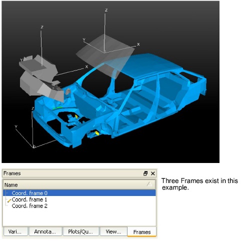
As EnSight reads in model Parts, they are all initially assigned to the same Frame of reference: Frame 0. Frame 0 corresponds to the model coordinate system (defined when the model was created). Using the Frame Mode, you can create additional frames, reassign Parts to different Frames, and specify various attributes of the Frames.
Normally, transformations you make on parts (rotations, translations, etc.) are performed globally; all Frames, Parts, and Tools are transformed with respect to the Global Axis origin and orientation. The Frame feature, on the other hand, allows you to perform transformations on selected Parts. This is useful if you wish, for example, to create an animation with Parts moving in different directions (such as a door or hood opening to reveal Parts within) or to move Part copies away from each other in order to color the Parts by different variables (in fact, if you make a copy of a Part, a new Frame is automatically created and the Part copy is assigned to it). The Frame feature coordinate transformations are visual only and occur only on the client. That is, the transformed coordinates cannot be used in the EnSight calculator.
In Frame Mode, transformations are always about the selected Frame's definition, that is, its origin position (with respect to Frame 0) and the orientation of its axes (with respect to Frame 0). Since this is the case, the Frame's orientation must be adjusted (if necessary) before any transformations are applied. If transformations are applied first, and the Frame's definition adjusted at a later time, the transformations will likely cause unexpected results (since the transformations originally performed were about a different axis definition than that about which transformations performed after the Frames definition changed occur). The necessary order is:
define frame location and orientation
assign part to frame
perform transformations relative to the frame
A Part can be assigned to only one Frame at a time. The Part will always be transformed by the Frame's transformation. A Part is not affected by a Frame's definition (other than transformations will be in reference to the definition). A Part's mirror symmetry operation (which can be thought of as a scaling transformation) is always about the Frame to which the Part is assigned.
The Tools (Cursor, Line, Plane, etc.) are always shown in reference to the selected Frame and are therefore also transformed by the selected Frame's transformations.
There are two transformation alternatives in Frame Mode: Frame Transform (the default) and Frame Definition. As pointed out earlier, a frame should first be defined (if necessary) before it is transformed.
A frame's visibility in the Graphics Window can be toggled on or off. A Frame may be selected by clicking on its axis triad or by selecting it in the Frames panel list.
By default, the Frame feature icon is not shown in the Feature ribbon. As discussed at the beginning of this chapter, it can be made to appear by right-clicking in the Feature ribbon and toggling Frames on in the menu. Its location in the ribbon can also be changed, by right-clicking in the Feature ribbon and selecting Customize Feature Toolbar.
For further discussion concerning the transformation of Frames: See Tool Transform)
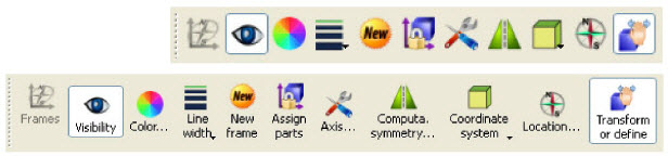
When a frame is selected, the following Quick Action Icons become available.
With and without text labels:
|
Visibility Icon |
Determines the visibility of the axis triad(s) of selected Frame(s). Default is Off |
|
|
Color... Icon |
Opens the Color Selector dialog for the specification of the color you wish to assign to a selected Frame's axis triad. |
|
|
Line width Icon |
Opens a pulldown menu for the specification of the width for Frame axis triad lines for the selected Frame(s).
 |
|
|
New frame Icon |
Creates a new Frame to which you can assign Parts. Be aware that each time you make a copy of a Part EnSight creates a new Frame and assigns the copy to the new Frame. If Parts are selected in the Parts list, the new Frame's origin will be positioned at the center of the selected Parts |
|
| Assign parts Icon |
Clicking this icon reassigns Part(s) selected in the Parts list to the currently selected Frame. |
|
|
Axis... Icon |
Opens the Axis area in the Feature Panel for the specification of axis triad line length and labels for the selected Frame(s).
 |
|
|
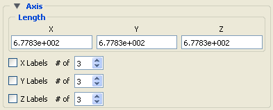
X Y Z |
These fields allow you to specify the desired length, in model coordinates, of each of the three axes of the selected Frame's axis triad |
|
|
X Y Z Label s Toggles |
Toggles on/off the display of Labels on the respective line of a selected Frame's axis triad. Labels show distance along each axis. |
|
|
X Y Z # of |
These fields specify the number of Labels which will appear on the respective axis. |
|
|
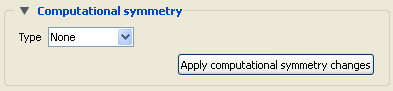
Computational symmetry... Icon |
Opens the Computational symmetry area in the Feature Panel for the specification of the type of periodic conditions which will be applied to all assigned Model Parts of the selected Frame. Note: Computational symmetry does NOT work on created parts.
 (see Set Symmetry) |
|
|
Apply computational symmetry changes |
Changes made in the dialog will not be applied until this button is clicked. |
|
|
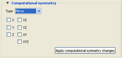
Type Mirror |
If type Mirror symmetry is chosen.
 |
|
| Mirror In |
Specification of the type of mirror periodicity |
|
|
Mirror X |
face-sharing quadrant on other side of the Y-Z plane |
|
|
Mirror Y |
face-sharing quadrant on other side of the X-Z plane |
|
|
Mirror Z |
face-sharing quadrant on other side of the X-Y plane |
|
|
Mirror XY |
diagonally opposite quadrant on same side of the X-Y plane |
|
|
Mirror XZ |
diagonally opposite quadrant on same side of the X-Z plane |
|
|
Mirror YZ |
diagonally opposite quadrant on same side of the Y-Z plane |
|
|
Mirror XYZ |
quadrant diagonally opposite through origin |
|
|
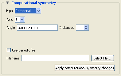
Type Rotational |
If type Rotational symmetry is chosen.
 |
|
|
Axis |
The Frame axis about which to rotate. |
|
|
Angle |
This field specifies the rotational angle (in degrees) about the selected Frame's z-axis for rotational periodicity. |
|
|
Instances |
This field specifies the number of periodic instances for rotational periodicity. |
|
|
Use periodic file |
If toggled On, the periodic match file specified in Filename is used for rotational symmetry. This is toggled on for non Case Gold format files. For case gold you must enter the periodic match filename into the Case file. |
|
|
Filename |
This field specifies the name of the periodic match file you wish to use. |
|
|
Select File... |
Opens the File Selection dialog for the selection of a periodic match file. |
|
|
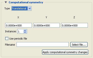
Type Translational |
If type Translational symmetry is chosen.
 |
|
|
X Y Z |
These fields specify the translational offset in reference to the selected Frame's orientation. |
|
|
Instances |
This field specifies the number of periodic instances for translational periodicity. |
|
|
Use periodic file |
If toggled On, the periodic match file specified in File Name is used for translational symmetry. Note: That this will be grayed out and unavailable for EnSight formatted data because this information should be found in the GEOMETRY section of the Case (.case) file (see Periodic Matchfile Format). |
|
|
Filename |
This field specifies the name of the periodic match file you wish to use. Note: This will be grayed out and unavailable for EnSight formatted data because this filename should be found in the GEOMETRY section of the Case (.case) file (see Periodic Matchfile Format). |
|
|
Select File... |
Opens the File Selection dialog for the selection of a periodic match file. |
|
|
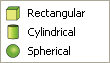
Coordinate System Icon |
Opens a pulldown menu for the selection of the type of coordinate system (rectangular, cylindrical, spherical) you wish to use for a selected Frame. All three are defined in reference to Frame 0, which is rectangular. Each frame's orientation vectors (which describe its orientation to Frame 0) are rectangular (as is their on-screen representation) no matter what the frame's coordinate system type. However, functions that access the frame will behave different depending on the frame's coordinate system type.
 |
|
|
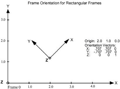
Rectangular |
The Figure below shows a rectangular frame. The origin is in reference to the Frame 0 origin, while the orientation is in reference to Frame 0's orientation.
 |
|
|
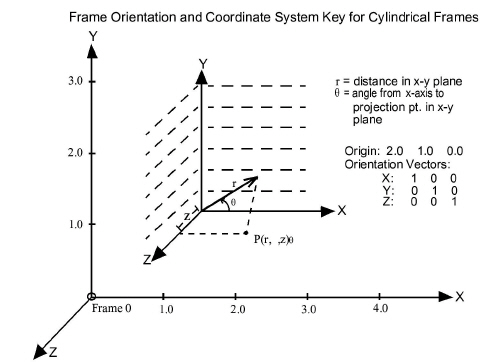
Cylindrical |
The figure below shows a cylindrical frame. The origin is in reference to the Frame 0 origin, while the orientation is in reference to Frame 0's orientation. Any function which accesses a cylindrical frame will do so in cylindrical coordinates:
 |
|
|
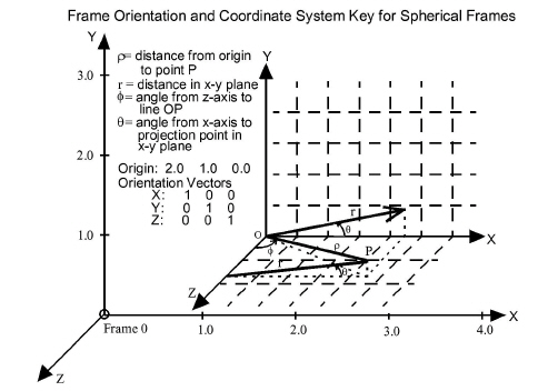
Spherical |
The figure below shows a spherical frame. The origin is in reference to the Frame 0 origin, while the orientation is in reference to Frame 0's orientation. Any function which accesses a spherical frame will do so in spherical coordinates:
 |
|
|
Location... Icon |
Opens the General area of the Feature Panel to permit precise definition of the selected Frame(s). See Frame Definition for a description of this dialog section. |
|
|
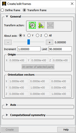
Transform or define Icon |
Toggles between the transform and define methods. |
|
|
Transform |
Transformations will cause the Parts assigned to the selected Frame(s) to be transformed as well as the selected Frame's axis triad. Translations will move the Frames' axis triad(s) and the assigned Parts. Rotations of Parts will take place about the selected Frame(s) axis origin. See Frame Transform |
|
|
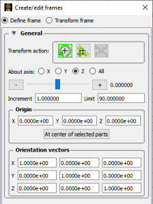
Definition |
User interaction in the Graphics Window or Feature Panel will modify the selected Frame(s) origin location and/or axis orientation. Note: Generally only want to use this mode before parts are assigned to the frame. See Frame Definition |
|


When Define frame has been chosen from the Transform or define icon or in the Feature Panel for frames, then actions you make will affect only the definition (origin and orientation) of the selected Frame(s). Frame 0's definition however, cannot be changed.

A Frame's definition should be adjusted before it is transformed under Frame Transform (as described in the previous pages). Transformations under Frame Transform are always about the Frame's origin and orientation. Failure to define the proper origin position and orientation of a Frame will result in unexpected transformation behavior.
You choose the type of transformation you wish to perform (rotate or translate) from the Transformation Control icons within the Create/Edit Frames Dialog.
Note: You cannot perform zoom, scale, or reset operations under Frame Definition.
|
Transform Action: Rotate |
||
|
Interactive Modification of Orientation |
When the menu in the Transforms icon is selected, clicking the left mouse button and dragging modifies the orientation of the selected Frame(s). Clicking on the end of the X axis will limit the rotation to be about the Y axis. Similarly, clicking on the end of the Y axis will limit the rotation to be about the X axis. |
|
|
Precise Modification of Orientation |
When the Feature Panel is opened under Frame Definition and the Rotate toggle is selected, the dialog will be configured to permit precise rotation (modification of the orientation) of the selected Frame(s).
You may rotate the selected Frame(s) precisely about their X, Y, Z, or All axes by clicking on the desired axis and:
|
|
|
Origin XYZ Orientation XYZ |
You may precisely position both the origin and the axis of a selected Frame by entering in the desired coordinates in the Origin and Orientation Vector X Y Z fields and then pressing Enter. These fields can be used regardless of whether the Rotate or the Translate toggle is selected. |
|
|
Transform Action: Translate |
||
|
Interactive Translation of Origin Position |
When this toggle is on, clicking the left mouse button and dragging will translate the selected Frame(s) (other than Frame 0) up, down, left, or right within the viewport. Holding down Ctrl while dragging will translate the selected Frame(s) forward or backward. |
|
|
Precise Translation of Origin Position |
When the Transformation Editor is open under Frame Definition and the Translate toggle is selected, the dialog will be configured to permit precise Translation (modification of the origin position) of the selected Frame(s).
You may translate the selected Frame(s) precisely along the X, Y, Z, or All axes by clicking on the desired axis direction and:
|
|
When Transform frame has been chosen from the Transform or define icon or in the Feature Panel for frames, transformations you make will affect the selected Frame(s) and the Parts assigned to them.
Note: Before any transformations are performed on a Frame, its definition should be modified (if necessary) as described later in this section. Transformations always occur about a Frame's origin and orientation. Failure to define the proper position and orientation of the Frame will result in unexpected transform behavior. Therefore, the order of dealing with things should be
define the frame
assign parts to the frame
transform according to the frame
You choose the type of transformation you wish to perform from among the Transformation Control icons in the Transformation Editor dialog. You cannot perform the zoom operation under Frame Transform.
|
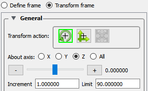
Transform Action: Rotate |
||
|
Interactive Rotation |
When this toggle is on, clicking the left mouse button and dragging causes the selected Frame(s) and all Parts assigned to the Frame(s) to rotate about the Origins of each Frame Axis. Holding down Ctrl while dragging will rotate the selected Frame(s) and all assigned Parts about a Z axis perpendicular to the screen. |
|
|
Precise Rotation |
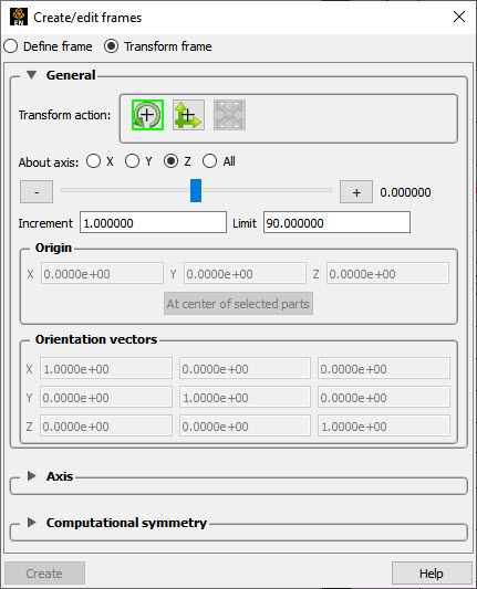
When the Transformation Editor is open under Frame Transform and the Rotate toggle is selected, the dialog will be configured to permit precise Rotation.
You may rotate the selected Frame(s) and assigned Part(s) precisely about the X, Y, Z, or All axes, as the orientation of the axes were defined when the Frame was first created by:
|
|
|
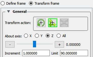
Transform Action: Translate |
||
|
Interactive Translation |
When this toggle is on, you can transform objects interactively in the X-Y plane (or by holding down Ctrl, in Z). Clicking the left mouse button and dragging will translate the selected Frame(s) and all assigned Part(s) up, down, left or right (or forward or backward) within the selected viewport. |
|
|
Precise Translation |
When the Transformation Editor is open under Frame Transform and the Translate toggle is selected, the dialog will be configured to permit precise Translation.
|
|
|
You may translate the selected Frame(s) and all Parts assigned to them precisely along the X, Y, Z, or All axes by:
|
||