


This section discusses the creation, management, and navigation within a Cave environment.
Configuration File (dconfig)
In order to configure a cave or a wall in EnSight, the user must create a
display configuration file. This file is specified on the command line using the argument
-dconfig <file> (see Command Line Start-up Options). If
<file> is not a fully-qualified path EnSight will search for the file in the following
directories:
~/.apex242/dconfig
$CEI/apex242/site_preferences/dconfig
These options allow for user-level and site-level configurations, respectively. There are two logical displays that can be configured in EnSight. The file is used to configure a detached display, which is external to the user-interface, and may consist of 1-36 regions configured to form a large continuous display. The configuration file also contains tracking calibration information and options for using 6D input devices. The following sections will address each of the capabilities related to parallel rendering and VR. The sample configurations described in this chapter can be found in the directory $CEI/ensight242/doc/dconfig. There are also examples of simulated configuration files, which allow you to simulate display to multiple graphics pipes on a single display.
Configuration File (dconfig) Format
Configuration files are text-based beginning with the line:
CVFd 1.0
# after the first line, anything following a '#' is a
    comment
The remainder of the file consists of one or more sections describing the displays and options. In describing the format of the file, portions which are optional will be surrounded by [].
The key factors are that (1) immersive displays are often not flat and (2) the rendered images must be co- registered with the coordinates of a 6d input tracking system.
Screen Layout
The basic syntax describing how screens are positioned in the cave:
display
[ stereo ]
screen
  [ hostid <h> ]
  displayid <p1>
  resolution <x-res> <y-res>
  [ displayorigin <xo> <yo> ]
  [ bottomleft <x> <y> <z>
    bottomright <x> <y> <z>
    topleft <x> <y> <z>
  ]
  [ lefteye or righteye ]
[ repeat 'screen' section for each additional screen
]
Note: All 3D coordinates given in the file are in the same frame of reference, and use the same units, as the tracking system. We will refer to this as "display coordinate space".
The keywords bottom/top refer to the minimum Y/maximum Y of the region, and left/right refer to the minimum X/maximum X of the region. In some cases 'bottom' may be near the ceiling, and 'top' may be near the floor, such as when a projector is mounted in an inverted position.
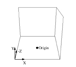
When determining the proper coordinates to use it is invaluable to sketch out the display environment, label the corners of each screen, and mark the location of the origin of the coordinate system. When using 6D input, the display coordinate system and the tracking coordinate system must be the same.
Example 13.1: Projectors Pointed at Screens
For the purpose of illustration consider the following example. Two projectors are pointed at screens which form a right angle, as illustrated below. The projected images are 10 feet wide by 7.5 feet high. The tracking system is calibrated in units of feet with the origin on the floor in the middle of the room.
CVFd 1.0
display
screen
   displayid :0.2
   resolution 1024 768
   bottomleft -5 0.0 –5
   bottomright 5 0.0 –5
   topleft -5 7.5 –5
screen
   displayid :0.1
   resolution 1024 768
   bottomleft 5 0.0 –5
   bottomright 5 0.0 5
   topleft 5 7.5 -5
Without head-tracking, this example is not yet very useful. The default position of the viewer is at (0,0,0), which is on the floor in the chosen coordinate system. There is an optional view section that can be inserted before the first screen of the configuration file to change these defaults:
view
   [ origin <x> <y> <z> ]
   [ zaxis <nx> <ny> <nz> ]
   [ yaxis <nx> <ny> <nz> ]
   [ center <x> <y <z> ]
   [ scale <factor> ]
   [ eyesep <d> ]
The origin specifies the position of the viewer,
and is only used if head- tracking has not been enabled. The zaxis and
yaxis are unit vectors that allow the specification of a default
orientation for objects placed in the scene. The default values are (0,0,-1) for
zaxis and (0,1,0) for yaxis. From the
origin vantage point, it is useful to think of
zaxis as the direction that the viewer is looking and
yaxis as the up direction.
The center and scale
parameters allow you to position and size the scene for your display. If these parameters are
not given, EnSight will compute a bounding box from the 3d coordinates given in the
bottomleft, bottomright, and
topleft parameters for the screens. The default center will be at the
center of this box and the default scale will be computed so that your EnSight scene will fill
the 3D space. Specifying a scale factor of 1.0 may be useful if your display coordinates were
designed to coincide with your model coordinates. This will allow you to view your models
life-sized. The values used to center and scale the data can be adjusted at runtime. See the
Edit Menu Functions for more details.
The eyesep parameter allows an exact setting of
the stereo separation between the eyes. It is half the distance between the eyes in the units
used by the head tracker.
Example 13.2: Positioning the Viewer at the Opposite Corner
Extending our example, we can position the viewer at the opposite corner of the room at a height of 5.75 feet:
CVFd 1.0
display
view
   origin -5 5.75 5
screen
   displayid :0.2
   resolution 1024 768
   bottomleft -5 0.0 –5
   bottomright 5 0.0 –5
   topleft -5 7.5 –5
screen
   displayid :0.1
   resolution 1024 768
   bottomleft 5 0.0 –5
   bottomright 5 0.0 5
   topleft 5 7.5 -5
Example 13.3: Test Large Displays and VR Environments on a Smaller System
It is relatively straightforward to test large displays and VR environments on a smaller system with a different number of graphics pipes. This can be accomplished by creating a configuration file that maps the pipes to smaller regions on a single monitor. As an example we will take the immersive configuration from Example 2 and modify it to run on a single display, with the modified regions shown in bold text.
CVFd 1.0
display
view
   origin -5 5.75 5
screen
   displayid :0.0
   displayorigin 0 0
   resolution 320 240
   bottomleft -5 0.0 –5
   bottomright 5 0.0 –5
   topleft    -5 7.5 –5
screen
   displayid :0.0
   displayorigin 320 0
   resolution 320 240
   bottomleft  5 0.0 –5
   bottomright 5 0.0  5
   topleft     5 7.5 -5
Note: This method makes use of the displayorigin parameter so that the
resulting windows do not overlap. The default value for displayorigin
is (0,0) for each pipe. In a similar manner it is also possible to simulate large display
walls on a single pipe.
Tracking and Input Devices
EnSight supports tracking and input with 6 DOF devices through a defined
API. Pre-built libraries are provided to interface with VRPN or trackd ((C) Mechdyne, Inc.,
www.mechdyne.com) on Windows and Linux, or the user may write a custom interface to other devices
or libraries. The tracking library is specified with the CEI_INPUT
environment variable.
The value of CEI_INPUT can either be a
fully-qualified path and filename or simply the name of the driver, in which case EnSight will
load the library libuserd_input-$(CEI_INPUT).so from directory:
$CEI/apex242/machines/$CEI_ARCH/udi/
Once any external programs are started, for example, a trackd or VRPN server, you can enable tracking in EnSight. From the Preferences → VR and User Defined Input, there is a toggle button which turns tracking on and off (see Edit Menu Functions).
For information on the API which allows you to interface to other tracking libraries or devices, please see the README file in $CEI/ensight242/src/cvf/udi.
Trackd
To select trackd, use:
setenv CEI_INPUT trackd (for csh or equivalent
users)
For the trackd interface you will also need to set:
CEI_TRACKER_KEY <num>
CEI_CONTROLLER_KEY <num>
in order to specify the shared-memory keys for the input library to interact with trackd. You can find the tracker and controller key values in your trackd.conf configuration file.
With the environment variables set, you are ready to activate tracking.
There are two parts to this. First, trackd operates as a daemon that is run independent of
EnSight. If your input interface includes a separate program, you can run it at this time. For
trackd users, it is often useful during configuration to invoke trackd with the
-status option, so that you can see the information on your input devices.
The trackd driver shipped with EnSight also has a debug mode that can be activated as follows:
setenv CEI_TRACKD_DEBUG 1
This is similar to the trackd -status option, but it
reports the input as seen by the EnSight trackd interface.
VRPN
To select VRPN, use:
setenv CEI_INPUT vrpn (for csh or equivalent
users)
VRPN is set up using a configuration file. Specify the path to the vrpn configuration file with an environment variable:
setenv CEI_VRPN_CONFIG [full path]/vrpn.cfg
The file is ASCII text and has the following format:
#VRPN 1.0
TRACKER (outnum) (vrpn_name) (sensor) (scale)
    (offset)
TRACKERVEC (outnum) dirx diry dirz upx upy
   upz
VALUATOR (outnum) (vrpn_name) (channel) (scale)
    (offset)
BUTTON (outnum) (vrpn_name) (button #)
DEBUG (0-4)
The file should start with the "#VRPN 1.0" string.
Afterward, the various commands follow. The text in parenthesis should be replaced by numbers.
The commands include:
DEBUG (level)
string. Afterward, the various commands follow. The text in parenthesis should be replaced by numbers. The commands include
TRACKER (outnum) (vrpn_name) (sensor) scale
   offset
Adds a tracker (numbered OUTNUM) to the UDI. The
tracker input is from a vrpn server using the name VRPN_NAME (in most
cases, this string looks like an email address). The specific sensor in the vrpn server is
selected using SENSOR. SCALE and
OFFSET are a linear transformation applied to the tracker position
before being presented to EnSight.
Note: More than one VALUATOR line that references the same
VRPN_NAME may be specified for different
OUTNUM values.
TRACKERVEC (outnum) dirx diry dirz upx upy
   upz
Refine the definition of the UDI tracker (numbered
OUTNUM). The dir{x,y,z} values define the
vector that is transformed via the vrpn transform to produce the
EnSight UDI
forward vector. The up{x,y,z} values define the
vector that is transformed via the vrpn transform to produce the
EnSight UDI up vector. The default values are: 0. 0. 1. 0. 1. 0.
Note: The line must be preceded by a TRACKER line with the same
OUTNUM value.
VALUATOR (outnum) (vrpn_name) (channel) (scale)
    (offset)
Adds a valuator (numbered OUTNUM) to the
UDI. The valuator input comes from the vrpn
remote analog server named VRPN_NAME. The specific
channel in the server is selected using CHANNEL.
SCALE and OFFSET are a linear transformation
applied to the valuator before being presented to EnSight.
Note: More than one VALUATOR line that references the same
VRPN_NAME may be specified for different
OUTNUM values.
BUTTON (outnum) (vrpn_name) (button_num)
Adds a virtual button (numbered OUTNUM) to the
UDI. The button input comes from the vrpn
remote button server named VRPN_NAME. The specific
button in the server is numbered BUTTON_NUM.
Note: More than one BUTTON line that references the same VRPN_NAME may be specified for
different OUTNUM values.
Example 13.4: Tracking and Input Devices
#VRPN 1.0
TRACKER 0 Tracker0@localhost 0 1.0 0.0
TRACKERVEC 0 0. 0. -1. 0. 1. 0.
TRACKER 1 Tracker0@localhost 1 1.0 0.0
TRACKERVEC 0 0. 0. -1. 0. 1. 0.
BUTTON 0 Mouse0@localhost 0
BUTTON 1 Mouse0@localhost 1
BUTTON 2 Mouse0@localhost 2
VALUATOR 0 Mouse0@localhost 0 1.0 0.0
VALUATOR 1 Mouse0@localhost 1 1.0 0.0
DEBUG 3
Config File (dconfig) Tracking Options
Once the EnSight client has been correctly interfaced to a tracking system you can add a section to the configuration file in order to calibrate the tracking with the display frame and customize the behavior of various interactions. The syntax for the section is:
tracker
  [ headtracker <i> ]
  [ cursortracker <i> ]
  [ selectbutton <i> ]
  [ rotatebutton <i> ]
  [ transbutton <i> ]
  [ zoombutton <i> ]
  [ xformbutton <i> ]
  [ xtransval <i> ]
  [ ytransval <i> ]
  [ ztransval <i> ]
  [ auxbutton <i> <j> ]
  [ motionfilter <i> <p> <r> ]
The headtracker and cursortracker parameters allow you to specify which tracking device is tracking head position and which is tracking the controller. Only two devices can be tracked by EnSight - one for the head position and one for the position of the controller. All button/valuator input is interpreted as having come from the controller.
Note: The EnSight API for input devices uses 0-based indices for trackers, buttons, and valuators. Trackd uses 1-based indices, and other libraries may differ as well.
The remaining options allow you to customize the behavior of buttons and valuators on the 6D input device. The input device can be used for:
Selecting items from the 3D graphical user interface, which includes the heads-up macro (HUM) panel, the part list, variable list, and value slider.
Performing transformations on the geometry in the scene.
Manipulating the cursor, line, plane, and quadric tools.
The input device has a local coordinate system which is relevant for some forms of 6D interaction:
The default mode defines button 0 as the select button. When the 3D is visible, you can point at the 3D buttons and the item that you are pointing at will be displayed in a highlight color. When you press the select button you will activate the current selection. For the HUM panel, this means that you will activate the macro that is defined for the selected button. See the User Defined Input Preferences found in Edit Menu Functions for more instructions on configuring and showing the HUM panel and part panel. Clicking on an item in the part list will select or unselect the item in the list. Combined with macros in the HUM, this will allow you to modify visibility or other attributes on a part or collection of parts. If there are many parts in the part list, you can also select the scrollbar and move the controller up and down to scroll through the list. Similarly, the part-value slider can be used to modify part attributes for certain part types. For isosurfaces you can select the part slider and move left to right to change the isovalue. When no parts are selected, the part-value slider can be used to modify the time in a transient simulation.
The , , and allow you to perform the selected transformations using gestures with the 6d input device. The allows you to link a button to the current transformation mode, similar to the mouse button configurations for the main interactions. You may want to add buttons on the heads-up-macro (HUM) panel to switch between modes. This is useful for 6D input devices with a smaller number of buttons.
Note: It is possible (and encouraged) to re-use the for a transformation. The is only used when you are pointing at a heads-up menu. When you are not pointing at a menu, the same button could be used as the , for example.
All 6d transformations have a sensitivity which can be set to control the speed at which the transformation occurs. These values can be set from the Edit → Preferences → VR and User Defined Input dialog (see VR and user defined input Preferences VR and user defined input Preferences in Edit Menu Functions). There are also two forms of rotation available. In Mixed Mode, the 6d device acts similar to a mouse for rotation. Once you click the rotate button, your movement is tracked in the X-Y plane of the input device. Your translation in this space is mapped to a rotation in the 3D space. In Direct Mode it is the orientation of the device, rather than the position of the device, which controls the rotation.
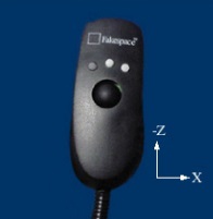
The xtransval, ytransval, and ztransval parameters configure the valuators to allow for translation of the scene by pressing the valuator in a given direction. The x, y and z designations refer to a local coordinate system which is fixed to the controller input device. As you hold the device in your hand, positive x is to the right, positive y is up, and positive z is toward the viewer. This local coordinate system depends on the orientation of the tracking device attached to the input device. It may be necessary to align the tracking device properly or modify the trackd (or other tracking library) configuration to achieve the proper orientation.
The parameters configure additional
buttons that can be used to control various options. The first parameter
"<i>" is the number of the to
define. The second parameter "<j>" is the physical device button to
bind to
<i>. Currently, is used by
EnSight as the Menu button. This button can be used to bring up the
User defined menu at the cursor point on the annotation plane. Pressing the
button a second time will either reposition the menu or it will pop up to the next level of the
menus if a submenu has been selected.
The motionfilter parameter allows the user to select a filter threshold for
each tracker (head or cursor). If the motion of the tracker exceeds this threshold, and EnSight
has the Fast Display mode global toggle enabled, it will display all the
parts using their fast representation until the motion drops below the threshold. The
<i> parameter selects the tracker to filter. The
<p> value specifies a threshold for the tracker position. This is
computed as the variance of the distance between the current position and the last 10 tracker
positions. Similarly, the <r> value specifies a threshold for the
tracker direction vector. This is computed as the variance of the angles between the current
direction and the last 10 directions (in radians).
Example 13.5: Basic Configuration with Head-Tracking
For the most basic configuration with head-tracking and a 6d input device, there are only three lines added to Example 2 to create the tracker section:
CVFd 1.0
display
view
   origin -5 5.75 5
tracker
   headtracker 0
   cursortracker 1
screen
   displayid :0.2
   resolution 1024 768
   bottomleft -5 0.0 –5
   bottomright 5 0.0 –5
   topleft    -5 7.5 –5
screen
   displayid :0.1
   resolution 1024 768
   bottomleft  5 0.0 –5
   bottomright 5 0.0  5
   topleft     5 7.5 -5
Example 13.6: Different Input Devices Available
There are many different input devices available, and some have additional buttons and valuators that can be used for navigation and selection in immersive environments. In this example the configuration file is extended to use different buttons for rotation, translation, zoom, and selection. We also configure a thumbwheel input to provide translation in the X-Z plane.
CVFd 1.0
display
view
  origin -5 5.75 5
tracker
  headtracker 0
  cursortracker 1
  selectbutton 4
  rotatebutton 0
  transbutton 1
  zoombutton 2
  xtransval 0
  ztransval 1
screen
  displayid :0.2
  resolution 1024 768
  bottomleft -5 0.0 –5
  bottomright 5 0.0 –5
  topleft -5 7.5 –5
screen
  displayid :0.1
  resolution 1024 768
  bottomleft 5 0.0 –5
  bottomright 5 0.0 5
  topleft 5 7.5 -5
Annotations
Annotations in EnSight include the heads-up macro panel, text, lines, logos, legends, and plots. In the display these items appear as an overlay which is fixed in screen space. In an immersive display environment it is useful to be able to specify the locations of these objects. In EnSight, these items continue to occupy a plane in the 3D world. By default, this plane will coincide with the first pipe in the configuration file. The user may choose to specify the position and orientation of this plane with the following addition to the configuration file:
Annot
  [ screen <n> ]
        OR
  [
  center <x> <y> <z>
  zaxis <x> <y> <z>
  yaxis <x> <y> <z>
  xscale <float>
  yscale <float>
]
Example 13.7: Annotations to Appear on the Right Wall Instead of the Left Wall
To continue with Example 13.6: Different Input Devices Available, suppose that the user would prefer for the annotations to appear on the right wall instead of the left wall. The following configuration file defines an annot section with the appropriate parameters to do this:
CVFd 1.0
display
view
  origin -5 5.75 5
tracker
  headtracker 0
  cursortracker 1
  selectbutton 4
  rotatebutton 0
  transbutton 1
  zoombutton 2
  xtransval 0
  ztransval 1
annot
  screen 1
screen
  displayid :0.2
  resolution 1024 768
  bottomleft -5 0.0 –5
  bottomright 5 0.0 –5
  topleft -5 7.5 –5
screen
  displayid :0.1
  resolution 1024 768
  bottomleft 5 0.0 –5
  bottomright 5 0.0 5
  topleft 5 7.5 -5
Fixing the annotations to a pipe is merely provided as a convenience. Internally this is identical to using the explicit form:
annot
  center 5 3.75 0
  zaxis 1 0 0
  yaxis 0 1 0
  xscale 10
  yscale 7.5
Cave Distributed Displays
Caves and walls can be driven by one or more machines. A single EnSight client can draw all of the screens in the dconfig file, or a separate EnSight client can draw each screen, typically on machines other than the one running the master client. The examples up to now set up a cave on a single machine.
A enshell network must be created to use distributed rendering. See Cave Environment, Wall Displays & Head-mounted Displays.
The dconfig file must be slightly altered to specify on which machine a client should run. In each screen section, a hostid line can be added, indicating the name of the machine to use, or indicating a enshell role.
Example 13.8: Cave Distributed Displays Example
CVFd 1.0
display
screen
   hostid clusternode01
   displayid :0.2
   resolution 1024 768
   bottomleft -5 0.0 –5
   bottomright 5 0.0 –5
   topleft -5 7.5 –5
screen
   hostid clusternode02
   displayid :0.1
   resolution 1024 768
   bottomleft 5 0.0 –5
   bottomright 5 0.0 5
   topleft 5 7.5 -5
Once a EnShell network is running, start EnSight in VR mode with the command line:
ensight -enshell -dconfig dconfig_file_name
Benefits of using a distributed system over a single machine:
- Rendering speed is higher because each client just draws one screen
- The number of screens is not limited to the number of display outputs on a graphics card.
Drawbacks of using a distributed system
- A enshell network must be created across all machines
- Some EnSight features are not supported in a distributed system, including adding or replacing a case, and restoring a context or session.
Tips for Distributed Rendering
EnSight must be installed on each machine where a client or server will run.
The rendering nodes on linux computers must have OpenGL enabled X11 servers running on them and they must be configured for direct rendering by remotely executed user processes. To test this, log into a rendering node remotely and run
glxgears -display :0. If this does not bring up glxgears on the display, the linux computer X11 server will need to be reconfigured.On Linux computers you may need to add options like
-acto the /etc/X11/xmd/Xservers file or otherwise configure X11 authorization mechanisms (we know it will run with -ac -s 0, but site security implications must be carefully considered). It may be useful to check that the rendering is direct as well (glxgears should run > 8000 fps on modern graphics cards with proper hardware accelerated OpenGL drivers). The output of glxinfo on the rendering node can be helpful in diagnosing issues as well. You may need to modify the permissions of the /dev/nvidiactl file(s) to allow a non-console app to access the graphics system.All Linux computers X11 screen savers and blanking functions should be turned off on the rendering nodes for your PC to work properly.
On Linux computers, ensure the DISPLAY environmental variable is set correctly, typically to
':0.0', set CEI to the proper path, and put $CEI/bin in the search path for remote connections (rsh or ssh).Many clusters have multiple TPC/IP address and hostnames for each node. Usually, one for the high-performance interconnect (for example, InfiniBand) and one for administration. For the highest performance EnSight needs to use the TCP/IP addresses associated with the high-performance interconnect. A cluster configured to use the highest performance interconnect as its default is the simplest to configure for use with EnSight. For example, since by default EnSight will use the TCP/IP address resolved by hostname, this name should be the highest performance interconnect.
Once the above are working on your cluster, contact Ansys Support if you run into any problems running EnSight on it. Please send us your cluster(s) details and the config files you have tried.
Some general advice
To simplify debugging, start small and scale up.
For example, we have seen problems with some TCP/IP over IB implementations, especially at scale, so start small (2-3 nodes) and if you have gigE in addition to IB, try that as well. Also, implement Enterprise (formerly HPC+) and VR with all the EnSight processes running on rendering nodes of a single cluster. Configure one rendering node on the cluster as an "interactive" node (with mouse/keyboard).