


This section discusses the creation, management, and navigation within Wall displays commonly referred to as a display wall, tiled display, or power wall.
A wall does not support head tracking or 6d input devices. If you have a wall and wish to incorporate head tracking, you can configure it as a cave with all screens positioned in the same plane (see Chapter 12.1, Cave Environment).
In order to configure a cave or a wall in EnSight, the user must create a display configuration file. See Configuration File (dconfig) for where to place the file.
The specification for a display wall consists of:
display
[ stereo ]
wallresolution
   <x-res> <y-res>
screen
   [ hostid <h> ]
   displayid <p1>
   resolution <x-res> <y-res>
   wallorigin <wall-x> <wall-y>
   [ displayorigin <xo> <yo> ]
   [ lefteye or righteye ]
[ repeat 'screen' section for each additional screen ]
The wallresolution section gives the total pixel
resolution of the display wall. For each graphics pipe, there will be a screen section that
describes the size (resolution) and position (wallorigin) of the region
within the global display. The displayid parameter specifies the X
display (i.e. :0.1). This parameter is ignored on Windows, because there is only a single
screen regardless of the number of graphics cards or video outputs. The
displayorigin is an optional parameter to specify the origin of the
window on the given pipe (default (0,0)).
Note: displayorigin is a position relative to the origin of a given displayid, while wallorigin is a position relative to the origin of the global display. Changing wallorigin will change the region of the wall that is visible in a given window, while changes to displayorigin simply move the window on the screen without changing the contents.
The example below will demonstrate a situation when the use of
displayorigin is useful. The lefteye/righteye optional designation can
be used for passive stereo displays, in which separate graphics pipes render the left and right
images.
Example 13.9: Using displayorigin
In this example there is one X server with five graphics pipes. The is displayed on pipe :0.0, with the other four pipes used for the detached display. Four projectors are configured in a 2x2 array to form a large continuous wall as illustrated:
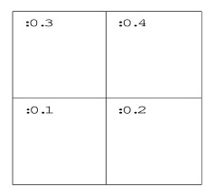
CVFd 1.0
#
# conference room display wall
#
display
wallresolution
   2560 2048
screen # lower-left
   displayid :0.1
   resolution 1280 1024
   wallorigin 0 0
screen # lower-right
   displayid :0.2
   resolution 1280 1024
   wallorigin 1280 0
screen # upper-left
   displayid :0.3
   resolution 1280 1024
   wallorigin 0 1024
screen # upper-right
   displayid :0.4
   resolution 1280 1024
   wallorigin 1280 1024
Example 13.10: Overlapping Images with Edge- Blending
It is not uncommon for displays walls to use overlapping images with edge- blending to smooth the otherwise sharp transition between projector images. The edge-blending is performed by the projectors directly. This is easily configured as a detached display by specifying pipes with overlapping pixel regions. Consider an example of two pipes at 1280x1024 resolution each, with an overlap of 128 pixels.
CVFd 1.0
#
# edge-blending example
#
display
wallresolution
   2432 1024
screen # left
   displayid :0.1
   resolution 1280 1024
   wallorigin 0 0
screen # right
   displayid :0.2
   resolution 1280 1024
   wallorigin 1152 0
Note: In this case the total resolution of the wall in the x direction is decreased by the amount of overlap.
Example 3
Passive stereo displays achieve stereo by projecting overlapping polarized images from multiple projectors. This can be achieved using detached displays with a distinct rendering region for each screen and eye. Consider for this example a single screen with two projectors. For illustration purposes we will assume that we have three graphics pipes. One pipe (:0.0) renders the main window and is not listed.
CVFd 1.0
#
# passive stereo display
#
display
wallresolution
   1280 1024
screen # left-eye
   displayid :0.1
   resolution 1280 1024
   wallorigin 0 0
   lefteye
screen # right-eye
   displayid :0.2
   resolution 1280 1024
   wallorigin 0 0
   righteye
Note: The lefteye/righteye parameters are NOT necessary when using traditional quad-buffered stereo to drive the projectors. Some systems have a signal splitter which takes the frame-sequential stereo signal and generates separate signals for left and right eye. In this case a conventional configuration file without the eye designations will work fine. Passive stereo displays are always in stereo mode.
Example 13.11: Active Stereo Displays
Active stereo displays achieve stereo by projecting alternating left and right eye images from a single projector, with glasses that alternately block the left or right eye. Adding the stereo line enables active stereo for all screens.
CVFd 1.0
#
# active stereo display
#
display
stereo
wallresolution
   1280 1024
screen
   displayid :0.1
   resolution 1280 1024
   wallorigin 0 0
Wall Distributed Displays
Walls are commonly driven by more than one machine. A single EnSight client can draw all of the screens in the dconfig file, or a separate EnSight client can draw each screen. In the preceding examples, a single machine rendered all of the screens.
See Cave Distributed Displays, which describes the addition of the 'hostid' line to a dconfig file, the use of enshell to launch the distributed processes, and pros and cons of running distributed. For trouble-shooting tips, see Tips for Distributed Rendering in the cave configuration section above.