


The following topics are included in this section:
Select the Part(s) that you wish to export in the main part list.
Select File → Export → Geometric Entities...
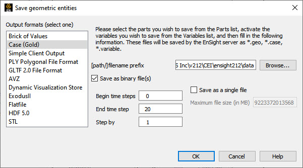
Be sure the desired output format is selected.
Follow the instructions given.
Enter a file root name.
If the dataset is transient, specify the beginning, ending, and step values.
For EnSight Gold only:
Toggle to save as binary files or not.
If the dataset is transient, you can choose to save the multiple timesteps in one file (one file per variable). If you choose this option, you can also specify the maximum file size.
Click .
Writers have access only to the geometry of selected parts and each of their active variables. The following writers exist only on the client: Simple Client Output, PLY, GLTF and AVZ. The remaining writers save the parts as they exist on the server. Parts that can be exported include all original model parts, as well as many of the created parts (such as 2D-clips, Elevated Surfaces, Developed Surfaces, and Isosurfaces).
The client writers save only the surface elements of the visible parts on the client file system, except for AVZ which saves all parts.
There are some important differences in how EnSight saves parts according to format chosen.
| Server writers | Client writers | |
|---|---|---|
| Which parts are saved? | All parts currently selected in the main Parts list (except those indicated below) | All visible parts |
| Saved from where? | EnSight server | EnSight client |
| Which parts cannot be saved? | Any client-based parts: contours, vector arrows, particle traces, profiles. | Filtered, limit fringe elements |
Select the 3D Part(s) (only 3D) to export.
Select → →
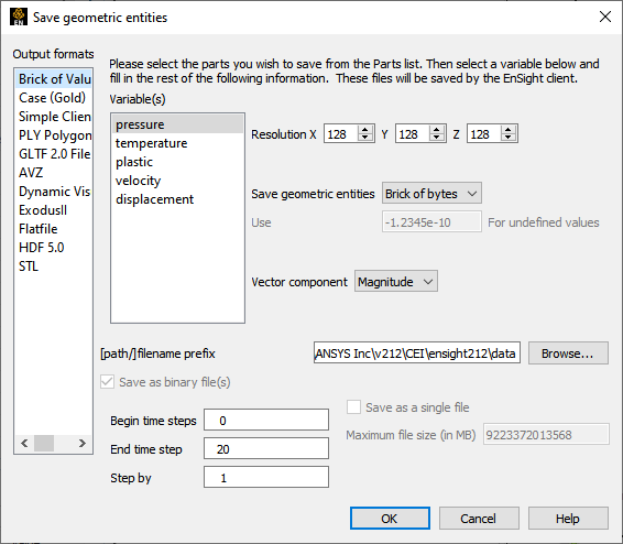
Be sure Brick of Values is selected under Output Formats (Select One).
Follow the instructions given.
Select the desired variable.
If the variable is a vector, select the component desired.
Select the sampling resolution.
Select the sampling format, Brick of Bytes or Brick of Floats.
Enter a file root name.
Click .
Brick of Bytes and Brick of Floats is intended to give you an interface mechanism to volume rendering codes for your 3D Part(s).
When you click the button the selected 3D parts are discretized to the resolution indicated using the box tool as the bounds and orientation (x/y/z resolution refers to the x/y/z directions for the box tool).
For Brick of Bytes (BoB) format a value of 0 is reserved for undefined (that is, the discritized point found no variable information). The value of 1 is tied to all variable values less than or equal to the minimum palette value tied to the variable chosen while 255 is tied to all values greater to or equal to the maximum palette value.
For Brick of Floats (BoF) format undefined values are assigned the undefined value indicated in dialog.
Both BoB and BoF files are written out without any metadata - only the values for the discritized points is written. The order of the data is according to the following pseudo code:
num_values = 0
for(z=0; z<z_resolution; ++z) {
  for(y=0; y<y_resolution; ++y) {
    for(x=0; x<x_resolution; ++x) {
      value_array[num_values] = value_at_this_location
    }
  }
}
write(file_name,value_array)Select File → Export → Geometric Entities...
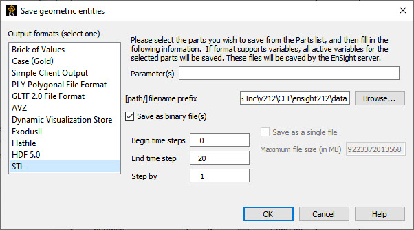
Be sure the desired output format is selected.
Follow the instructions given.
If the writer accepts parameters, enter any desired ones in the Parameter(s) field.
Enter a file root name.
Toggle to save as binary files or not.
If the dataset is transient you can choose to save the multiple timesteps in one file (one file per variable). If you choose this option, you can also specify the maximum file size.
Click .
The user-defined writers can call the routines of an EnSight API to retrieve, for example, nodal coordinates, node ids, element ids of parts selected in the Parts window, to be passed by value to be used, manipulated and/or written out in any format desired. The User-defined writer dialog includes a Parameter field that allows the passing of text into the writer from the user. This text could contain extra options which the writer understands.
Several example writers (including source code header files, Makefile and the corresponding shared library) are included to demonstrate this capability.
The Case (Gold) Lite writer is included to demonstrate how to exercise most of the API and output a subset of the Case (Gold) format. Complex numbers and custom Gold format are not supported with this writer. The Case (Gold) writer ignores the Parameter field. While the writer is not compiled, the source code of this writer, the required header files, and the Makefile are included.
The Flatfile user-defined writer is designed to
demonstrate the output of selected part nodal data (coordinates & IDs) as well as active
variable values (scalar and/or vector only) in a comma delimited format easily imported into
other applications. If any of the keywords 'ANSYS' or
'force' or 'body' is entered into the
Parameter field, then Flatfile will output an
Ansys body force file. It ignores the binary toggle and only writes ASCII files.
The STL user-defined writer is designed to write out the border geometry in the form of triangular 2D elements of the selected part(s) at the beginning timestep. The end time and the step time are ignored. The STL format does not support multiple parts in a single binary file, but does support multiple parts in a single ASCII file. Therefore, if multiple parts are selected and ASCII is checked, the STL writer outputs an ASCII file with the border of each of the parts. If multiple parts are selected and binary is checked, the STL writer outputs a binary file containing a single border of the multiple parts. The STL writer only saves the beginning timestep and ignores the End Timestep and Step By fields. The STL writer ignores the Parameter field.
The Dynamic Visualization Store (DVS) user-defined writer exports the currently selected
parts and the active variables to .dvs format. The binary option, and
single file format fields are all ignored. This writer currently does not support structured
parts, tensor and complex variables. Such objects are skipped during the export operation.
Enter COMPRESSION=1 to COMPRESSION=9 in the
Parameter field to turn on compression for the DVS export. Higher
COMPRESSION will spend more time trying to reduce file size.
Note: The DVS export, unlike other writers, will currently append data into a cache by default and not overwrite the data. You must manually delete the cache folder to remove data before exporting to the same folder.
There are some important differences in how EnSight saves parts according to format chosen.
| User Defined Writers (UDW) | |
|---|---|
| Which parts are available to the UDW? | All parts currently selected in the main Parts list (except those indicated below) |
| Where are the available parts located? | EnSight server |
| Which parts are unavailable to the UDW? | Any client-based part: contours, vector arrows, particle traces, profiles |
More user-defined writers may be distributed with EnSight in the future.