The following topics are included in this section:
EnSight textures can also be used as multi-dimensional palettes to allow the user to control the color and opacity of a part based on arbitrary functions of two variables. The key to this technique is generating the appropriate texture map. In the following example, we will use a texture map found in the data directory with the "cube" model.
Load the cube model and bring up the variable calculator. We will need to create an S and a T variable that will be used to access the texture.
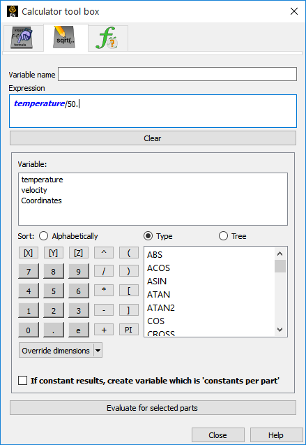
In the calculator create a new variable named S with the expression temperature/50.0 (this puts 'S' roughly in the range [0,1]).
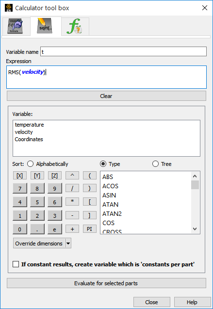
Create a variable T that is the expression RMS(velocity).
Create an xyz clip of the mesh as a 'Z' clip and turn on shaded display.
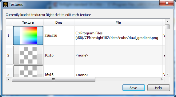
With the clip_plane part selected, open the Part Color/Surface Property Editor, Textures turndown, and click on the button. Load the file dual_gradient.png, included in the directory with the cube dataset, into the first slot.
Note: This texture is an opacity ramp along the X axis and a color ramp along the Y axis.

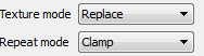
Set the Texture mode to Replace and the Repeat mode to Clamp.
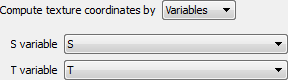
Now, set the Compute texture coordinates by option to Variables and pick S and T as the S and T variable names.
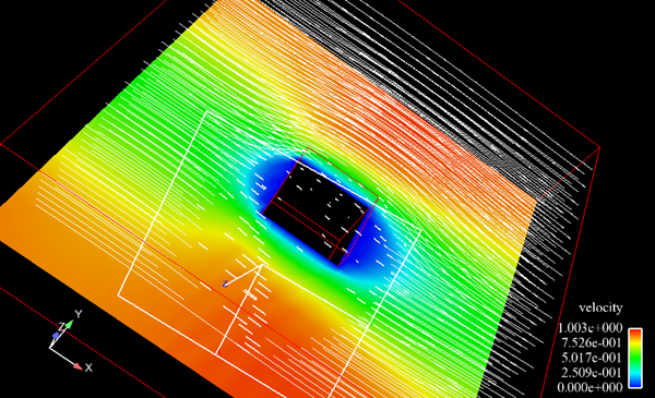
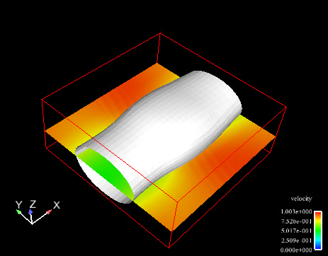
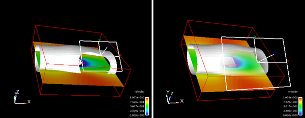
The display will look like the image shown, depending on the placement of the clip plane. The coloring is relative to the Velocity of the field, while the opacity of the plane is relative to the temperature of the plane. This type of technique can be used with any two variables; the key is generating a 2D texture map that is meaningful for ranges of the two variables in question.
Textures can also be used to manipulate the transparency of portions of objects in interesting ways. In this example, a texture image with only an alpha channel will be used to clip into a part to reveal parts inside of it.
Load the cube dataset again. And as in the textures as palettes example:
Load the image files 'circle.png' and 'sphere.png' into two texture slots. In both cases:
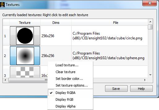
Use the right mouse button menu to set the textures' border color. Change the border color alpha channel value to 255 and view only the alpha channel.
Note: The RGB channels are white, but there is a dark region in the alpha channel of the images.
Create an isosurface of temperature in the mesh as well as a 'Z' plane clip.
Color the plane clip by velocity.
Now, select the isosurface part and much like the logo example, use the plane tool to project the texture onto the isosurface.
In this case, use the circle texture and modulate texture mode and set the repeat mode to clamp.
The texture will clip through the isosurface as a projected circle (from the circle in the texture) to view parts interior to it. The sphere texture provides a smoother clip. Experiment with other textures and repeat modes for other effects. Remember that each part can have its own texture, each with a different set of projection settings for highly expressive visual options.
Here is an example of a clipping texture applied to dynamic particle traces. The tracer pulses are not clipped, but the traces are clipped to a projected circle texture as in the example.