


Texture mapping is a mechanism for placing an image on a surface or modulating the colors of a surface by various manipulations of the pixels via a texture map image. EnSight supports the application of a texture onto a part and the combining of texture effects with the normal EnSight coloring schemes. This can include animated textures(for example, .evo or .mpeg files), which can be used to texture parts and 2D annotations.
The simplest use is to place a decal/logo or photograph on the surface of a part. Texturing can also be used to add repeated patterns, provide custom transparency and lighting, color a part by multiple variables and clip parts to arbitrary boundaries. A texture operation in EnSight consists of a texture map image, a collection of interpolation and blending options and a mechanism for projecting the texture map image onto a part. Each of these items is described in the following sections. Shown below is a quick overview from the Surface Property Editor to add a texture.
Putting a Logo or Image on Part(s)
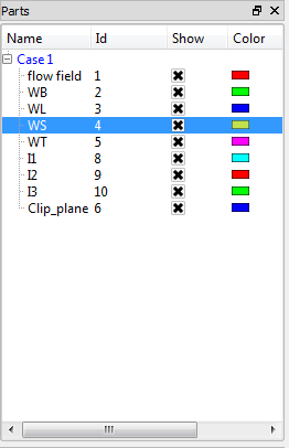
Select the desired part(s) in the main Parts list.
Click on the color wheel icon at the top to open the Surface Property Editor dialog.

Pulldown the Texture.
Click on Edit textures to open Textures dialog.
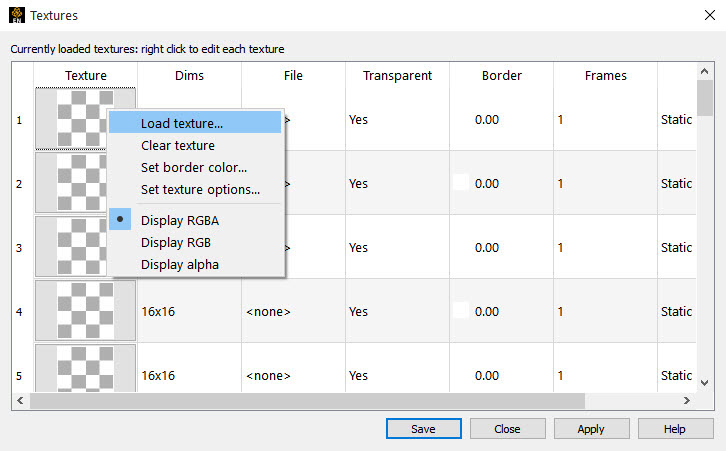
In the Textures dialog, right click on Texture and choose to load an image from file, to be used as a texture.
Pick a texture number to apply.
EnSight supports up to 32 different textures, which are displayed as thumbnails down the Texture column in Textures dialog.
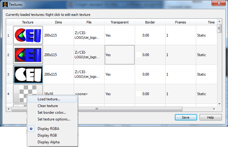
A number of operations can be performed on the textures by right-clicking on the thumbnail image and selecting from the menu.
A new image or movie (for example, .evo, .mpeg, etc.) can be set for the texture using the option.
A texture can be reverted back to the 16x16 transparent checkerboard default pattern using the menu.
Each texture has a border color that is used for colors outside of the texture bounds. This color (RGB and opacity) can be set explicitly using the menu.
Advanced options for loaded texture images and animations can be set using the menu (see the Texture options section below).
The basic information for the currently selected texture is displayed in the text field below the thumbnails. The size of the texture, its source, border color and the nature of its transparency (A channel and border color) is displayed.
The 32 textures are numbered one through 32. Each part in EnSight can have one of the 32 texture associated with it. This can be done by selecting the part(s) and either clicking on the appropriate button thumbnail or selecting the number from the option menu.
All textures have both a color (RGB) and an opacity (A) component. By default, the thumbnail is drawn using the full RGBA pixel value. Options at the bottom of the right-click menu allow the user to select which channels to draw: Display RGBA, RGB, or Alpha. The first three images in the example dialog above are all the same texture, but drawn with a different function.
The the first image is the full RGBA image,
the second one is just the RGB part of the image
and the third one is just the A part of the image.
Notice how the A channel masks out the black and white pixels in the RGB image. This masking can be used to place non-rectangular images/icons on EnSight parts.
Users often make use of a common set of textures for many different analyses (for example, company logos, standard palettes, etc). The button allows the user to save the currently loaded selection of textures and their display mode into the user's preferences directory. These will be automatically loaded every time EnSight is launched.
Setting Texture Options
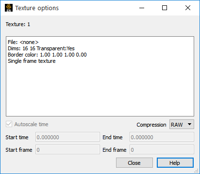
In EnSight, animated textures (for example, .evo or .mpeg files) can be used to texture parts and 2D annotations. Each animated texture is linked to the current solution time in EnSight. This temporal mapping can be set by right-clicking on the logo, choosing Set texture options to see the Texture options dialog.
Basic information about the texture is presented in the upper pane.
This includes the filename, border color, dimensions, and number of frames in the texture. It also includes temporal reference information for animated textures.
Animated textures have a start and ending frame number. These can be used to “crop” the texture to some subset of the animation.
There is also a starting and ending solution time for the texture. The frame from the texture is selected such that the starting frame number is used when the current EnSight solution time is at or before the texture start time and the ending frame is used when the current solution time is at or after the ending time. The temporal mapping is linear in-between.
There is also an Autoscale option.
If this option is set, the starting and ending time for that texture will always be set to the dynamic range of currently loaded EnSight solution times.
Note: EnSight will read the entire animation into memory when it is loaded. If the movie is large, it can use a significant amount of memory. In memory, EnSight uses lossless compression schemes for the data. The current scheme can be changed using the Compression options pulldown.
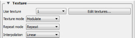
The Texture mode, Repeat mode and Interpolation scheme define how textures are accessed and how they are integrated into the normal EnSight coloring scheme.
The Texture mode determines how a texture is combined with the natural coloring scheme in EnSight. The pulldown has three options: Replace, Decal and Modulate.
In Replace mode, the base colors provided by EnSight are ignored and the texture is used as the only source of color for the part (note, this has the side effect of disabling any lighting).
In Decal mode, the alpha channel of the texture is used to select between the texture color and the base color of the part. If the texture alpha value is 0, the base color of the part is displayed, while locations where the texture alpha value is 255, the texture color will be used exclusively. All alpha values in-between 0 and 255 will result in an interpolation between the texture and base colors.
Note: The default texture uses an alpha channel with values 255 and 80.
In Modulate mode, the base color is multiplied by the texture color and the resulting texture is used. Modulate mode is commonly used with a texture that has a color of white and some pattern in the alpha channel. This allows the base color to show through, but varies the transparency of the part. Arbitrary clipping operations can be set up this way. Modulation of the color channels can be confusing as the operation tends to suppress colors, but it can be used with a grayscale texture to attenuate.
The Repeat mode allows the user to control how the texture repeats outside the texture coordinates [0,1]. The pulldown has three options: Repeat, Clamp, or Clamp to texture.
In Repeat mode, the coordinates are repeated (for example, a texture coordinate of 2.3 is mapped to 0.3) so that the texture repeats itself, and the border color is not used.
In Clamp mode, coordinates outside of [0,1] are fixed to the border color of the texture. If repeat mode is set to repeat, Clamping is often used for logos and explicit texture coordinates (see Texture Projections) that you wish to see only once.
In Clamp to texture mode, coordinates outside of [0,1] are fixed to the edge value of the texture. The border color is not used.
The Interpolation scheme is applied when the graphics hardware needs to access a pixel in the current texture. The pulldown has two options: Linear or Nearest.
Linear interpolation mode generally results in smoother looking displays, but can result in "fringes" that are the result of interpolating to colors that might not exist in the native texture. Linear can be slower, but in EnSight, this is often the result of the fact that a part may be turned translucent and need to be sorted during rendering (See Texture Implementation Limitations).
Nearest will result in the exact colors in a texture using the nearest neighbor interpolation method. It is less smooth and has starker contrast.
EnSight provides two mechanisms which may be used to define where a texture should appear on a part. The first is by Projection.

In this mode, it helps to think of the texture as a projected light-source, like a presentation projector, only without divergence (i.e. the light lines are parallel). The user places the light source to shine through the scene at some orientation centered at some point. Textures are not limited to the exposed surface in EnSight, thus any surface that intersects the beam of light is textured.
The user can enter the values for this projection in the S vector, T vector and Offset fields in the dialog.
These define a vector in the space of the part that will correspond to the directions of the X and Y axis of the texture image as well as a point of focus for the texture.
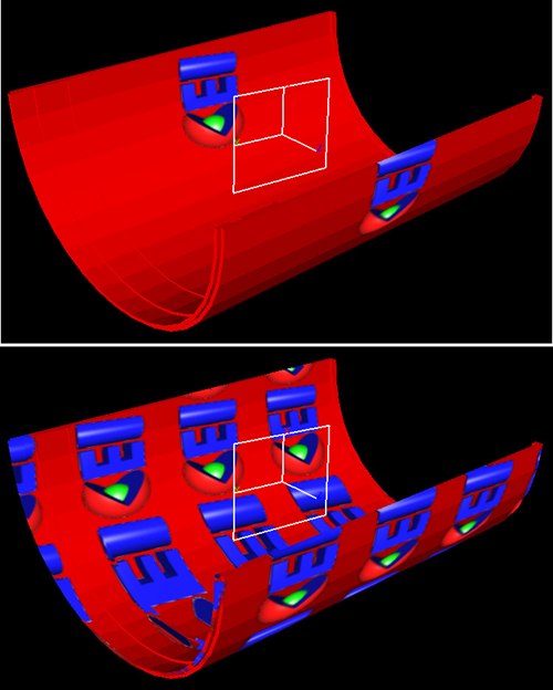
Perhaps the simplest method for setting these values is to use the plane tool. Place the plane tool in the view to match the desired projection. The texture will be scaled to fit in the boundaries of the plane tool with the texture axis aligned with the tool X and Y axis. The texture itself is projected along the Z axis of the tool. Once the tool has been placed, click on to fill in the dialog fields.
The will move the plane tool to the projection formed by the current dialog values.
The example below illustrates the placement of a logo, in decal mode with clamp and repeat modes set. Notice that the texture appears both in front of and behind the tool.
The texture projection can also be specified relative to a point or a collection of points.
The Projection option menu in Absolute mode will set the texture projection to the current settings which places the texture at an absolute position and attitude in space. If the part geometry moves or deforms, the texture remains fixed in the scene, therefore it appears to move on the part surface.
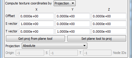
Choose Projection Offset relative to ID, to specify a node ID in the Origin field. The Offset X,Y,Z values are considered to be relative to this node ID. If it moves in time, the texture projection will translate with this node.
Likewise, Projection Offset and S/T vecs relative to node Ids allows for three node Ids to be specified, causing the projection to rotate and scale with the relative positions of those nodes.
If you turn on these relative modes, you may need to click to set up the field values to match the plane tool again (The option always honors the current relative projection and node IDs, if provided).
The second form of projection EnSight supports is via Variables.
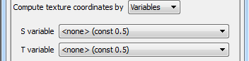
In this mode, one or two scalar variables are used to provide explicit S and T texture coordinates for texturing. This is the most general mechanism for texturing. The S-variable and T-variable option menus provide a list of possible scalar variables.
Users may also set the S and/or T value to the constant quantity 0.5. The variables are generally in the range [0,1], which map to the edges of the texture map, just inside the border. Values outside this range will either be mapped to the texture border color (in the case of clamp mode) or will be warped back into the range of [0,1] by repeated subtraction/addition (in repeat mode). This form of projection is capable of emulating the previous model. It also makes it relatively easy to create two dimensional data palettes. Just like the existing palette in EnSight, some function of a variable is used to select a color from a table. In this case, the table is a 2D texture, so this can be done for two different variables at the same time, and the opacity can be varied as a function of those variables.
All forms of EnSight part displays can be textured: surfaces, lines, points, etc. Of special note, in "variable" mode, points are rendered with a single texture coordinate, regardless of the form they are displayed as. Thus, a point displayed as a sphere can only use a single pixel sample from a texture. Thus, to place a logo on a point rendered in sphere mode, one would need to use projection mode.