


To probe interactively:
Click the Probe Feature icon (or select > ).

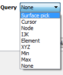
Set the Query pulldown to desired operation.
Surface Pick: Interpolate to any picked position on the surface of the model.
Cursor: Interpolate to location of cursor tool within the model.
Node: At a specific node number.
IJK: At a specific IJK location.
Element: At a specific element number.
XYZ: At a specific XYZ location.
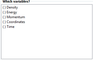
Select the desired variable(s) to display.
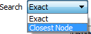
If Query is set to Surface Pick, you can select:
Whether the probe will snap to closest node (which will show node id).
OR
Use exact location (which will show nearest element ID).
And whether the information will be sampled:
When you click the P keyboard.
OR
Continuously as you move the mouse.
If Query is set to Node, Element, IJK, or XYZ, enter Node ID or values needed followed by Enter. If Query is set to Cursor, move the cursor tool to desired location and press the P key (while the mouse is in the graphics window).
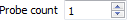
Enter a value controlling the number of simultaneous probe markers displayed. Once this number has been reached, the oldest marker is replaced by each new marker.
If the selected variable is a vector variable, you can specify which component (or the magnitude) of the variable is displayed.
In addition to having the results displayed on the model in the graphics window, you can open a table that displays the results.
When done, change the Query to None to disable interactive probing.
Probes are displayed as a marker (sphere) and the query text label. The appearance of the marker and label can be changed:
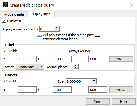
Click the Display Style tab.

Toggle visibility for the query text label. Label size is set in the annotation preferences (see Setting Annotation Defaults).

Set the color of the label.

Toggle visibility for the probe marker.
Set the color of the marker.
Toggle visibility for the id label. (Node id, element id, etc.)

Toggle whether query text labels are Always On Top (never hidden by geometry) or occluded by geometry that is closer.

Set the radius of all probe markers.
It is possible to extract the elements that contain the query locations, if element ids exist:
After creating a query open the Display Style tab.
Click the up arrow for the Display expansion factor.
An expansion factor of 1 indicates that the elements that contains the query will be extracted and shown.
Click the up arrow again.
An expansion factor of 2 indicates that the elements from step 2 will be shown along with the elements that neighbor these elements.
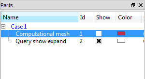
Since the expansion factor feature uses a subset part, if you wish to display the subset part differently (such as turn on node labels) this can easily be done through the subset part attribute editing. The name of the subset part in the part list will be Query show expand.
If you wish to keep the subset part that was the result of the display expansion factor setting, you may do so when you turn off the interactive query. A pop-up dialog will ask you if you wish to keep or delete the expansion factor subset part.