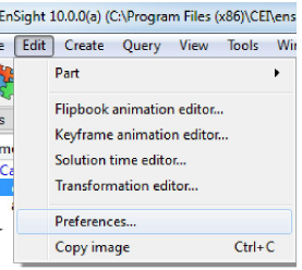
Bring up the Preferences dialog by selecting from the pull-down menu.
The following preference categories are available in the Preferences dialog (and will be explained below):
Need to make the font bigger everywhere in EnSight?
Select Annotation from the Preference Categories list.
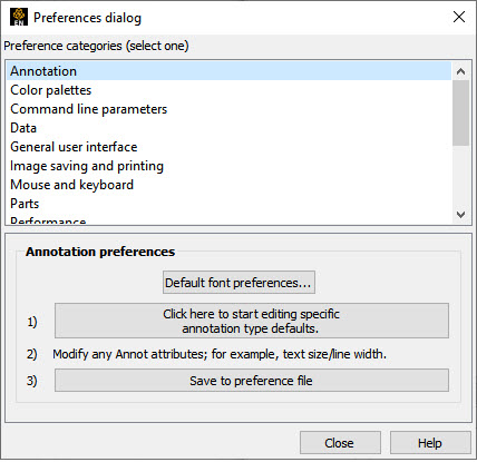
Click on the button.
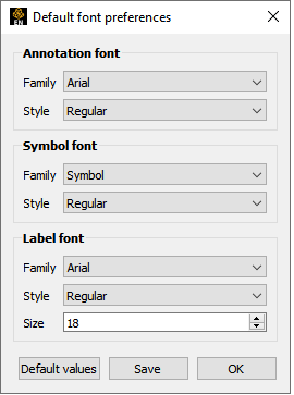
Change the annotation, symbol and label fonts individually.
Change the size.
Click to save the preferences.
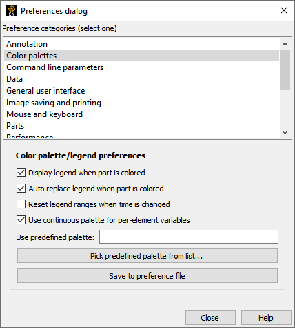
Select Color Palettes from the Preference Categories list.
Display legend when part is colored
Toggle on if you want the color legend to automatically appear when you color a part by a variable.
Auto replace legend when part is colored
Toggle on if you want color legends to be replaced when the current legend is no longer in use (that is, no parts are colored by the variable) and a new variable is in use.
Reset legend ranges when time is changed
Toggle on if you wish the legend ranges to be updated when time is changed, thus based on values of variable at the current time.
Use continuous palette for per-element variables
Set the default legend for per element variables to be constant over the element or to vary continuously over the element (averages with neighbors).
Use predefined palette
If you have predefined color palettes, you can set one of them to be the default by entering the name or picking one from the list of defined palettes.
Click .
A number of command line parameters exist for EnSight. These parameters can be set in your preference file so you do not have to specify them on the start line each time you use EnSight.
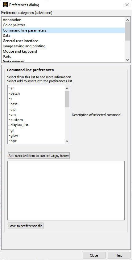
Select Command Line Parameters from the Preference Categories list.
Command Line Preferences
Select a command line argument.
An explanation of the selected argument will appear in the dialog.
Add selected item to current args, below
Click here to add the parameter.
It will be placed in the edit area.
If you make a mistake and add an unwanted parameter, simply highlight it in the feedback area and delete it.
If additional information is required, a note will be posted here to help you.
If you need to add additional information, add any text needed into the edit area.
Click to save the preferences.
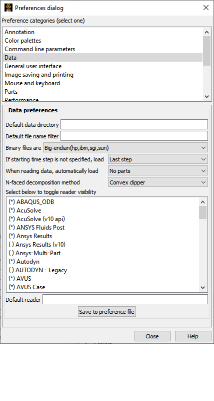
Select Data from the Preference Categories list.
Default data directory
If you want to specify a path to look for data, specify it here.
Binary files are
You can specify the default binary file type here.
If starting time step is not specified, load
When transient data is loaded into EnSight you can choose to specify a beginning time step. If you do not specify a beginning time step, either the first or the last time step will be loaded depending on this preference.
When reading data, automatically load
After successfully reading data into EnSight you are presented (for most data formats) with a part loader if this attribute is set to No Parts. If set to any other attribute the parts specified will be loaded and displayed without intervention from the part loader.
N-faced decomposition method
Sets the n-faced polyhedron decomposition algorithm (for detailed description, see Edit Menu Functions)
New data notification
When solver solution is proceeding and new timestep files appear this will prompt you to include the new files as additional timesteps - only for Case Gold format. Please contact Ansys Support regarding this option.
The readers shown with a * will show up in the pull-down for data format in the EnSight data reader dialog. You can take readers off of the pull-down list if you toggle the * off (select the reader in the list).
Default reader
You can specify the default data type by typing in the exact name of the reader.
Click to save the preferences.
Select Image Saving and Printing from the Preference Categories list.
Click the button. This will bring up the Print/Save Image dialog.
Modify the attribute you want for your preference such as the image format.
Click Save to preference file to save the preferences.
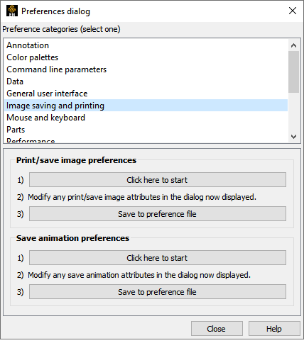
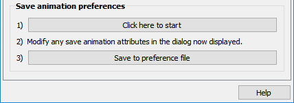
Select Image Saving and Printing from the Preference Categories list.
Click the button under Save animation preferences. This will bring up the Save animation dialog.
Modify the attribute you want for your preference such as the number of Keyframes.
Click Save to preference file to save the preferences.
This preference allows you to modify the behavior of the mouse buttons used during EnSight transformations. Several different actions are available for the various single click, multiple button single click, and double click options.
Note: It is required to set at least one button to Selected transform action (which means that the button is set to the action as shown in transformation icons at the bottom of the EnSight dialog - set to rotate by default). Also, one mouse or the P key must be set to Selected pick action.
Select Mouse and Keyboard from the Preference Categories list.
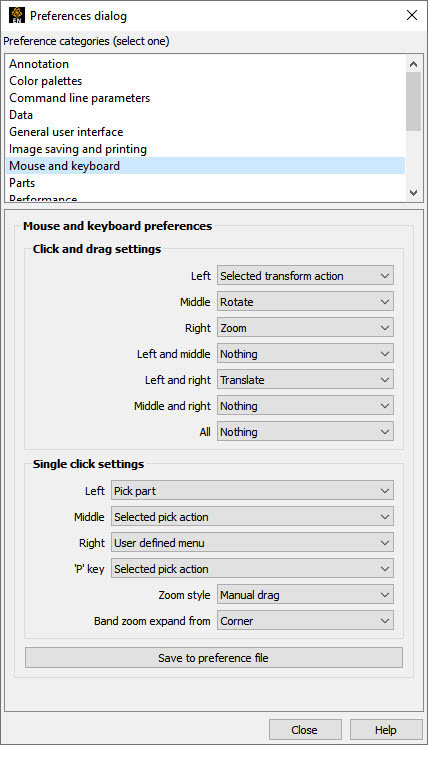
Modify the preference for each of the mouse buttons (and keyboard P key).
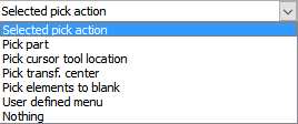
Single click actions available are:
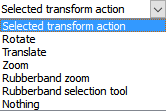
Click and drag options are:
See Produce Customized Pop-Up Menus for a description of what "User defined menu" is.
Select Performance from the Preferences Categories list.
When the geometry is built for display, optimize it for faster rendering. Turning Optimize geometry for graphics performance will take a little bit of extra time when the part is built. Well worth the extra processing time if the part will be displayed multiple times. However, if you are stepping through time (and thus only displaying the part one time per frame), you might consider turning this off.
To set fast mode to static, toggle on Static fast display. The default is off meaning that the fast display (that is, bounding box) is only active during transformations such that the image returns back to full graphics display when the mouse buttons are not depressed. In static mode the fast representation is continuously displayed.
To ensure proper display of transparent geometry, EnSight must sort all the transparent polygons in the display. This can be an expensive operation, particularly if multiple transparent parts are visible. Transparency sorting controls when and how surfaces are sorted.
In Interactive mode, sorting is performed between every redraw of the view. In Delayed mode, sorting is not performed while the user is interacting with the view (while the mouse button is held down).
Note: Hidden line overlay does not work with either Interactive or Delayed.
In Depth peeling mode (which is only available on graphics cards that support the OpenGL Shading Language) sorting is done by the graphics card on a per-pixel basis by rendering the view repeatedly. This mode scales better as the number of polygons increases and it does not suffer a performance hit when multiple parts are transparent. The number of peels (and hence the number of surfaces to order properly) is controlled by the Number of peels field.
Specify Point Resolution (1-100) if using point display for fast display mode.
Set Sparse model resolution (1-100) if using sparse geometry display for fast display mode.
(Only used if immediate mode is being used.)
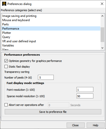
EnSight is a client-server architecture with the possibility that the two processes are executing on different and possibly remote machines. Due to this, a general abort function is not possible. Instead a timer abort function is available that will terminate many server operations after a set amount of time has passed. If you wish to set this time-out value turn the toggle on and set the time-out amount (in seconds).
Click Save to preference file to save the preferences.
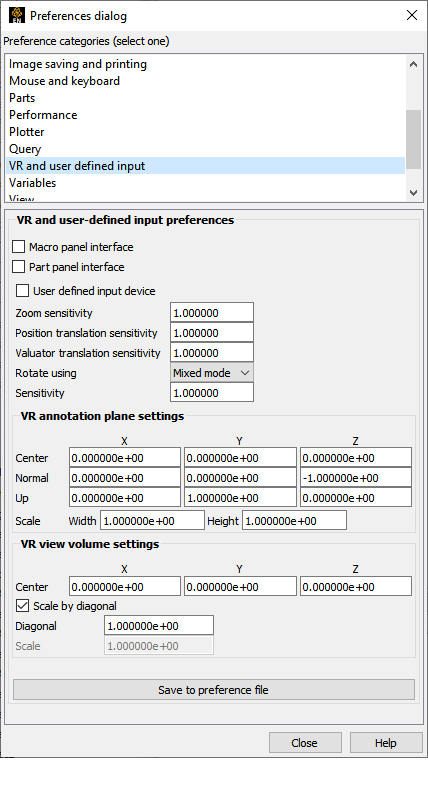
Select VR and User Defined Input from the Preferences Categories list.
Turn Macro panel interface on to show the macro panel display.
Toggle Part panel interface to select the default to display a part list in the graphics window. This is especially helpful in full screen mode or a VR environment.
Turn User defined input device on to activate the user defined input device (
ENSIGHT10_INPUTmust be set to the proper device).Zoom sensitivity sets the sensitivity for the zoom operation. The values for zoom are scaled by this setting, so values larger than 1.0 will make the inputs larger while less than 1.0 will make them smaller.
Mixed mode will use the input devices z rotate directly but use x and y translation values for x/y rotations. Direct mode will use the rotation angles from the input device directly for all three axis.
Sensitivity will set a scaling factor for the rotation values.
Click Save to preference file to save the preferences.
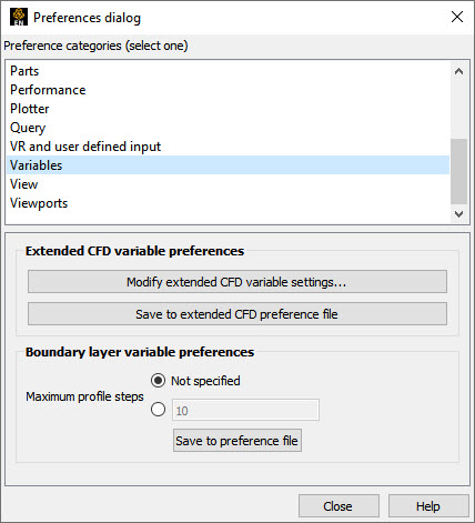
Select Variables from the Preferences Categories list.
Brings up the dialog for setting extended CFD settings. Save these settings by clicking Save to extended CFD preference file.
Boundary Layer calculation
Recommendation: let EnSight determine the maximum number of profile values from the surface to the edge of the boundary layer.
Manually changing this value allows clamping of the number of sample points in the profile off the wall into the flow field. Since each sample point is approximately equivalent to the center of each cell in the boundary layer sub-mesh, if the number of cell layers in the boundary layer sub-mesh is known, this would be a good value so the profile does not exceed this limit. Warning: Setting this value too low can cause the sampling to terminate before the edge of the boundary layer is reached, thus wrongly predicting the values of interest.
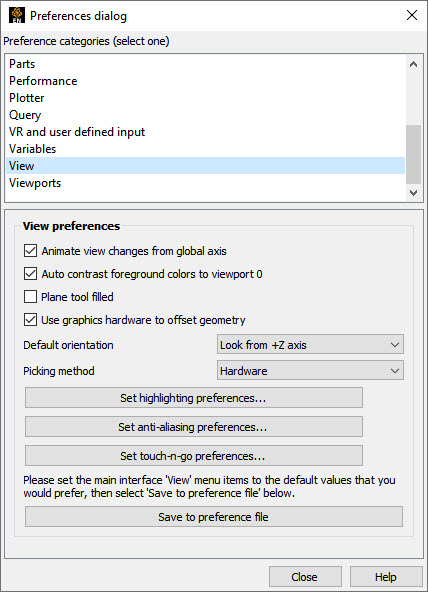
Select View from the Preferences Categories list.
Auto contrast foreground colors to viewport 0 switches white and black foreground colors for maximum contrast with Constant and Blended backgrounds for viewport 0.
Turn Plane tool filled on if you want the plane tool to be shown as a transparent plane, or off if you want it shown in line drawing mode.
There are two offsets employed in EnSight. The first one, hardware offset, is perpendicular to the monitor screen, and done in hardware if this toggle is on. This will allow, for example contour lines to appear closer to the viewer than their parent part so they are visible no matter what orientation the part is viewed from. The second offset is the display offset. The display offset can be set in the feature panel for line parts such as contour lines, particle trace lines, vector arrows, and separation/attachment lines. The display offset is the distance in the direction of the element normal (perpendicular to the surface).
Select the default viewing orientation.
For newer graphics cards leave Picking method as Hardware and EnSight will attempt to use hardware picking, and if not available will use software picking. For older graphics cards with sluggish performance, choose Software.
Click Set highlighting preferences... to bring up dialog controlling selection feedback in the graphics window
Click Set anti-aliasing preferences... to bring up dialog controlling the anti-aliasing parameters.
Click Set touch-n-go preferences... to bring up dialog controlling the click-n-go preferences.
Click Save to preference file to save the preferences.
Important: If you save Software picking and later change to a newer graphics card, you must change this back to Hardware to take advantage of the new card.
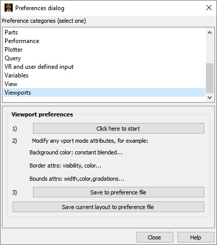
Select Viewports from the Preferences Categories list.
Press on Click here to start. This will bring up the Viewports dialog with all the viewport items selected.
Set any viewport attribute (for example, background color to blended).
Click Save to preference file to save the attributes set in above in item #2 to the preference file as defaults for future sessions.
Click Save current layout to preference file to save the current viewport layout to the preference file.