In many types of analysis, multiple parts are used to distinguish between various components or material types. To the extent allowed by the particular data format, EnSight maintains this distinction by assigning these entities to separate model parts. In some cases, however, this distinction is no longer useful for post-processing. When manipulating objects in EnSight, you often want to apply the same attributes or operators to a group of parts. If the group is large, this process can become unwieldy. Fortunately, EnSight provides a mechanism, called grouping, for grouping multiple parts into a single group part. The original parts comprising the group will no longer be visible in the list.
In this example, we will group all parts associated with the car into a single part.
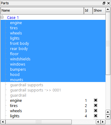
Select all the parts associated with the car; place the mouse pointer over the first part in the Parts list, click the left mouse button, then hold down Shift and left-click on part 12. You should now have the first twelve parts selected in the list.
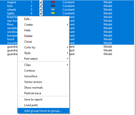
Right-click the list of parts and select .
In the pop-up dialog enter
caras the group name (replacing the default name of ), and click . You will now see a hierarchy in the Parts list with a group called car and parts 1 - 12 included in that group.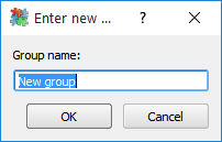
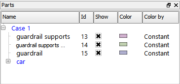
The interesting parts are now the four parts in the Parts list: three parts for the guard rail and the new group part (named car).
EnSight can displace geometry based on the value of a vector variable. Each displacement vector represents a translation of a node from its original position (an offset).
Select all of the parts in the Parts list. This can be done multiple ways:
Click the Case1 line in the Parts list which will select all the parts in the Case1 group
Right-click any part and ->
From the main toolbar → →
.
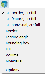
Click the Part Element Settings icon in the Quick Action Icon Bar for parts and select 3D border, 2D full from the pulldown.
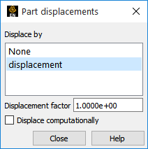
Click the Displacement icon in the Part Quick Action Icon Bar to open a variable chooser dialog for displacement.

Select the displacement variable, then close the dialog.
Note: Note the new positions of the car and the guard rail. See Display Displacements ( → ) for more information.
Now color the car by the plastic strain variable. Below, we do this operation by using the user interface dialogs. Another way to do this would be to right-click the car group and then .
Select the car group in the Parts list.
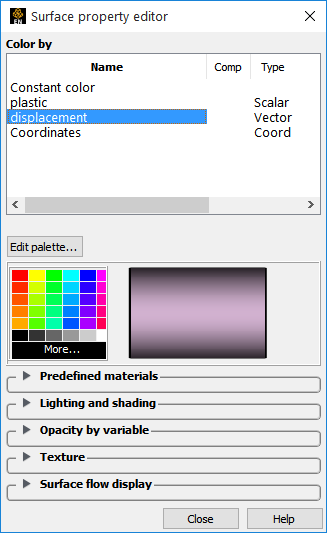
Click the Color/Surface Property icon in the Quick Action Icon Bar to open the Part color, lighting, & transparency dialog.

Select the plastic variable from the list, then close the dialog by selecting the X in the upper right corner.
The color legend appears to the right of the model in the Graphics Window. Color legends have many display attributes – see Create Color Legends ( > ) for more information.
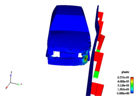
Rotate and zoom the model until the view in the Graphics Window looks something like the image below:
Toggle OFF the Highlight Selected Parts Icon.

EnSight provides an interactive probe tool that uses the mouse pointer to select points
Click the Probe Icon in the Feature Icon bar to open the Feature Panel.

Select the plastic variable.
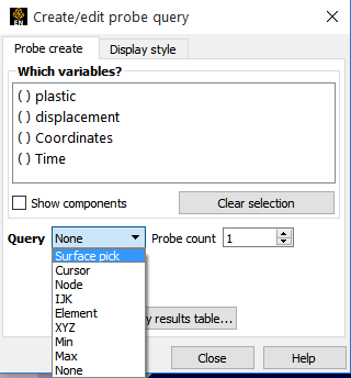
Change the Query to Surface Pick.
Move the mouse pointer into the Graphics Window and place the pointer over the car (preferably in a non-blue region). Press the P key.
The value of the plastic strain variable is calculated for the point under the mouse and displayed. A marker (the sphere) is also displayed.
Change the Query back to None.
See Probe Interactively (Help → How to manual...) for more information.
By default, EnSight initially displays the last time step. However, it's easy to change timesteps.
The Solution Time panel provides several methods for working with time. Perhaps the easiest way to change time steps is to use the slider bar.
Place the mouse pointer over the slider bar. Click the left mouse button and drag the bar until the value in the Current field is
12.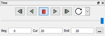
Release the mouse button.
Note: The geometry in the Graphics Window has updated to reflect the data at the new time step. See Change Time Steps (Help → How To Manual ...) for more information.
EnSight provides powerful query and plot features. Query/plot is fully integrated with the transient data handling facility so that plots will automatically update during time changes. Here we will query for the maximum plastic strain over all timesteps using right click functionality to perform the task.
Select the car group in the Parts list.
Right-click the plastic variable in the Variables list. You may need to open the Scalars to see it.
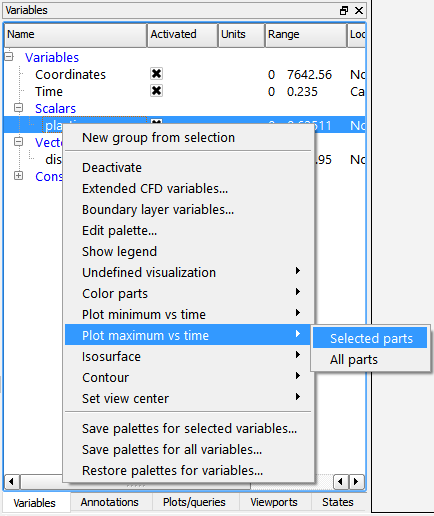
From the right-click pulldown choose → .
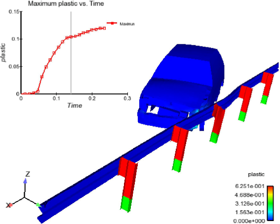
The plot appears in the upper left corner of the Graphics Window.
See Query/Plot and Change Plot for more information.
Your Graphics Windows should now look like the following: