The shock tube has found widespread use as an experimental device in which to investigate chemical kinetic behavior in reactive gas mixtures. Much can be learned by experiment alone, however such investigations are enhanced considerably when done in concert with computer simulations. To this end, the Shock Reactor Model simulates the chemical changes that occur after the shock heating of a reactive gas mixture. The Shock Reactor Model is designed to account for both incident and reflected normal shock waves. It makes allowances for the non-perfect gas behavior, boundary-layer effects and detailed finite-rate chemistry.
Shock provides flexibility in describing a wide variety of experimental conditions. Often people who perform shock tube experiments report their experimental conditions differently. The Shock Reactor Model allows input of these different conditions directly, without requiring hand calculations to prepare the input. The Shock Reactor Model works together with the Gas-phase Kinetics package.
The input options to the Shock Reactor Model coincide with the parameters most likely to be measured in shock tube experiments. For incident shock cases, the incident shock velocity and any two of the density, temperature and pressure, either before or behind the shock, can be specified. For reflected shocks, any two of the density, temperature and pressure behind the shock can be specified or conditions for the incident shock can be given. If the reflected shock velocity is specified, it is used in determining the temperature and pressure of the gas mixture behind the shock. Otherwise, the application determines that reflected shock velocity (and associated temperature and pressure), which renders the gas behind the shock at rest. Whenever gas conditions before the shock are given, the Shock Reactor Model calculates conditions behind the shock from the Rankine-Hugoniot equations using real gas thermodynamic properties for the test gas mixture.
A shock tube is a device in which a
gas at high pressure (the driver
gas) is initially separated from a gas at lower pressure
(the test gas) by a
diaphragm. When the diaphragm is suddenly burst, a plane shock wave propagates through the
test gas raising it to new temperature and pressure levels. At the elevated temperature and
pressure, chemical reaction commences. As the shock wave
moves through the test gas, a rarefaction wave moves back
into the high-pressure gas at the speed of sound. The test gas and the driver gas make contact
at the " contact
surface, which moves along the tube behind the
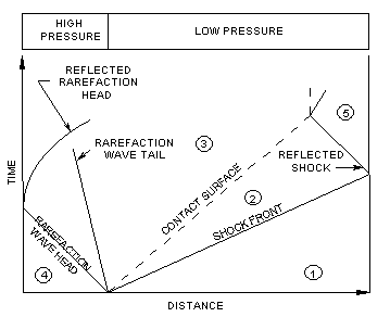
shock front. Conventional notation represents the
conditions in the unperturbed, low-pressure test gas by
the subscript 1, so that the initial temperature and pressure in this
region are denoted as  and
and  , respectively. The region between the shock front and the contact surface is
denoted by subscript 2 ; the region between the contact surface and the
rarefaction wave by subscript 3. The initial conditions on the
high-pressure side are given the subscript 4. If the shock wave is
allowed to undergo reflection at the end of the tube, the pressure conditions in this region
are given the subscript 5. Figure 7.1: Adistance-time diagram of a shock experiment
shows the ideal movement of the
shock front, the contact surface, the rarefaction wave and the
reflected shock wave
in a distance-time diagram.
, respectively. The region between the shock front and the contact surface is
denoted by subscript 2 ; the region between the contact surface and the
rarefaction wave by subscript 3. The initial conditions on the
high-pressure side are given the subscript 4. If the shock wave is
allowed to undergo reflection at the end of the tube, the pressure conditions in this region
are given the subscript 5. Figure 7.1: Adistance-time diagram of a shock experiment
shows the ideal movement of the
shock front, the contact surface, the rarefaction wave and the
reflected shock wave
in a distance-time diagram.