


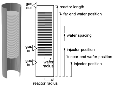
The reactor and wafer temperature model is a transient two-dimensional set of equations describing a large row (approximately 100 to 300 wafers) of regularly spaced wafers placed along the axis of symmetry of the cylindrical reactor, as shown in Figure 7.1: Schematic of multi-wafer reactor . The wafers are contained within a quartz process tube that is externally heated by a series of segmented cylindrical electrical heaters. The heaters are independently controlled by reactor thermocouples. The quartz process tube is sealed at the ends with doors to maintain reactor pressure and the backsides of the doors and heaters are insulated. An additional quartz (liner) tube is placed between the wafers and the quartz process tube.
The following approximations are made in developing the model:
Because multi-wafer LPCVD reactors operate at high temperature (approximately 900 K) and low pressure (approximately 0.1 Torr), heat transfer between the process tube and wafers is dominated by radiation exchange and the effects of gas-phase convection and thermal emission are not important in determining the wafer temperature. Hence, assuming that the wafer emissivity does not vary significantly during the deposition process, the wafer temperature can be determined without considering the gas-phase transport within the reactor.
Because the wafers are thin, the temperature variation across the thickness of a wafer is neglected and heat conduction is only considered in the radial direction through the wafers. By similar argument, the quartz walls are thin and therefore the temperature variation across the walls is neglected and only heat conduction in the axial direction considered through the quartz tubes. The reactor heaters and adjoining insulation are modeled as two concentric cylinders with both axial heat conduction in each cylinder and radial heat conduction across the heater-insulation boundary.
The transmissivity of silicon is small for temperatures greater than 600 K and hence the silicon wafers are treated as opaque. Due to the highly polished nature of the wafer surfaces, they are treated as specular reflectors with radiative properties independent of wavelength.
The quartz process tube is treated as semitransparent with diffuse surface reflection and radiative properties that are independent of wavelength.
All other surfaces in the reactor are treated as opaque diffuse reflectors with wavelength-independent properties.
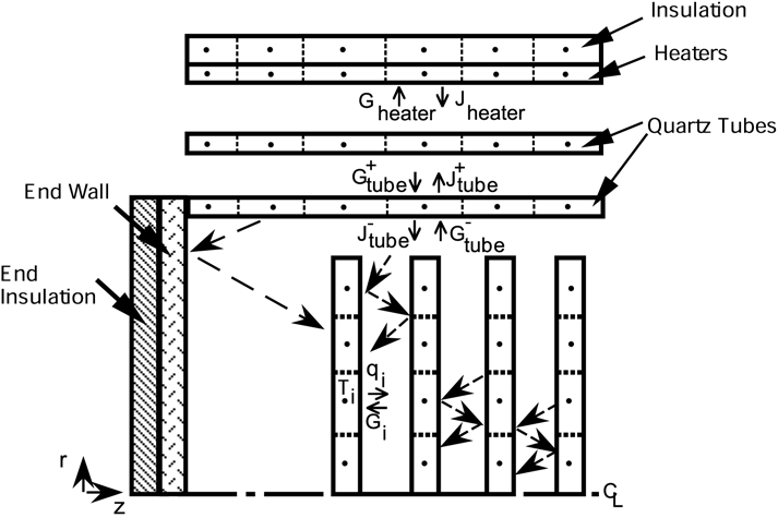
Figure 7.1: Schematic of multi-wafer reactor shows an expanded diagram of a typical group of three wafers located near the front of the large wafer load. The general governing equation for transient heat conduction in the wafers, quartz tube, heaters, and insulation is of the form
 | (7–1) |
where  and
and  are the density and specific heat of the particular material, and
  is the local
heat flux
vector. The
is the local
heat flux
vector. The  term is used to represent the rate of
thermal
energy production per unit volume in the heaters due to electrical dissipation, when considering heat conduction in other components of the reactor it is set to zero. Finite-difference equations for one-dimensional heat conduction within the wafers are formulated by fitting a non-overlapping series of
term is used to represent the rate of
thermal
energy production per unit volume in the heaters due to electrical dissipation, when considering heat conduction in other components of the reactor it is set to zero. Finite-difference equations for one-dimensional heat conduction within the wafers are formulated by fitting a non-overlapping series of  radial control cells (dashed lines) across each of the wafers. For the quartz tube, heaters, and insulation, a similar set of one-dimensional control cells is defined along the axial coordinate (see Figure 7.1: Schematic of multi-wafer reactor
). The temperature of each cell is defined at the grid point located at the center of each cell. At each end of the reactor, two control cells for the reactor door and its insulation are also defined.
radial control cells (dashed lines) across each of the wafers. For the quartz tube, heaters, and insulation, a similar set of one-dimensional control cells is defined along the axial coordinate (see Figure 7.1: Schematic of multi-wafer reactor
). The temperature of each cell is defined at the grid point located at the center of each cell. At each end of the reactor, two control cells for the reactor door and its insulation are also defined.
An energy balance is performed for each cell by integrating Equation 7–1 over each type of control cell in accordance with the finite-volume method described by Patankar. [3] At faces of the control cells where heat conduction occurs, the heat conduction flux is approximated by Fourier’s law. At control cell faces that lie on radiating surfaces the heat flux is computed by considering the net radiation exchange with the surrounding surfaces.
For opaque surfaces such as the wafers, the net radiation heat flux leaving the surface of an element may be expressed as
 | (7–2) |
where  is the emissivity of the wafer material,
  is the Stefan-Boltzmann constant, and
  is the irradiation incident on the i
th surface of a wafer cell. The amount of irradiation incident on a wafer element from other surfaces in the reactor is computed by using the net-radiation exchange method. The expressions for irradiation on the wafer cells are of the form
is the irradiation incident on the i
th surface of a wafer cell. The amount of irradiation incident on a wafer element from other surfaces in the reactor is computed by using the net-radiation exchange method. The expressions for irradiation on the wafer cells are of the form
 | (7–3) |
 | (7–4) |
where  is the local radiosity leaving the inside of the tube wall directly next to the wafer and
  is the local irradiation on the outside of the tube wall. The variables
  ,
,  , and
, and  are the emissivity,
reflectivity, and
transmissivity of the semitransparent quartz tube. The variables
are the emissivity,
reflectivity, and
transmissivity of the semitransparent quartz tube. The variables  ,
,  and
and  are the respective specular shape factors for wafer-to-wafer, wafer-to-tube, and tube-to-tube radiation exchange. The radiation heat flux absorbed on the outer rim of a wafer is applied as a boundary condition at the outer radius of a wafer.
An approximate expression for the absorbed heat flux is
 | (7–5) |
where  is the temperature of the wafer rim and
  is the irradiation on the wafer rim.
The specular shape factors for the calculations, which can in general be written as  , represent the fraction of diffuse energy leaving a surface
  and arriving at surface
  by the direct path and all possible paths involving intermediate specular reflections from other surfaces in the reactor. In the present model the reactor quartz tube is considered to be a semitransparent diffuse gray emitter, while the wafer surfaces are treated as opaque, diffuse emitters and specular (mirrorlike) reflectors. In order to simplify the calculation, interior wafers in the load are only allowed to exchange radiation with the portion of the tube wall located directly above them.
The wafers are treated as specular reflectors and therefore specular shape factors between the wafers and reactor surfaces must be computed by summing the direct contributions from surface images created by the mirror-like reflections from the wafers (see Figure 7.2: Schematic of model layout for multi-wafer reactor ). The reflected images of the surfaces were constructed using a ray tracing procedure discussed in Siegel and Howell. [4] The appropriate expressions for the specular shape factors are of the form
 | (7–6) |
 | (7–7) |
 | (7–8) |
where the terms  ,
,  , and
, and  are used to represent the direct exchange factors between the
k th reflected images of a wafer or
tube element and the particular surface element in question.
The direct exchange factors are computed from analytic expressions found in Siegel and
Howell[4]
and Howell [5].
are used to represent the direct exchange factors between the
k th reflected images of a wafer or
tube element and the particular surface element in question.
The direct exchange factors are computed from analytic expressions found in Siegel and
Howell[4]
and Howell [5].
Radiant energy balances between the quartz process tube and the heaters are also computed by the net radiation exchange method. For the semitransparent quartz process tube the radiosity leaving an element on the outside of the tube,  , is of the form
 | (7–9) |
where  is the axial coordinate of the center of the i th area element on the tube and
  and
and  are the respective irradiances on the outer and inner walls of the tube. The radiosity leaving a surface element on the heaters is of the form
 | (7–10) |
The irradiation incident on a surface element of the quartz tube or heaters can be expressed in general as
 | (7–11) |
where  is the diffuse configuration factor between surface element
  and
and  , and the summation occurs over all surface elements
  in the field of view of surface
  . The net radiative
heat flux leaving a surface element is computed from the radiosity and irradiation and is given by an expression of the form
. The net radiative
heat flux leaving a surface element is computed from the radiosity and irradiation and is given by an expression of the form
 | (7–12) |
If the radiosities are known on the tube and heater surface elements then Equation 7–10 can be used in conjunction with Equation 7–11 to compute the net radiative heat flux on the surface of each element. The radiosities are computed by substituting the irradiation given by Equation 7–10 into Equation 7–8 and Equation 7–9 to obtain an equation for the radiosity leaving each surface element on the heater and quartz tube. Because of reflection and transmission between the surfaces, the radiosity of each surface element is dependent on the radiosities from all other surface elements as well as it own temperature. In accordance with the net radiative exchange method, this results in a linear system of equations for the radiosities, which can be expressed in matrix form as
 | (7–13) |
The  matrix depends only on the surface element radiative properties
  and the shapefactors between elements. The
  matrix depends only on the element radiative properties, element shapefactors,
and the temperatures of the elements. This linear system of equations is solved by using either
the Twopnt [6] or
DASPK [7], [8] numerical methods. For a given estimate of the element surface temperatures, the lower and
upper triangular matrices are used to compute the surface radiosities by backward substitution.
The radiosities are then used in Equation 7–10
and Equation 7–11
to compute the net radiative
heat flux on the surface elements of the quartz tube and heaters. These radiative heat fluxes are
then used in the finite volume form of Equation 7–1
to compute an energy balance
for the temperature of each element on the quartz tube or heaters. Energy balances are also
formulated for the insulation elements where the convective and radiative heat flux leaving the
exterior surface of the insulation is given by an expression of the form
matrix depends only on the element radiative properties, element shapefactors,
and the temperatures of the elements. This linear system of equations is solved by using either
the Twopnt [6] or
DASPK [7], [8] numerical methods. For a given estimate of the element surface temperatures, the lower and
upper triangular matrices are used to compute the surface radiosities by backward substitution.
The radiosities are then used in Equation 7–10
and Equation 7–11
to compute the net radiative
heat flux on the surface elements of the quartz tube and heaters. These radiative heat fluxes are
then used in the finite volume form of Equation 7–1
to compute an energy balance
for the temperature of each element on the quartz tube or heaters. Energy balances are also
formulated for the insulation elements where the convective and radiative heat flux leaving the
exterior surface of the insulation is given by an expression of the form
 | (7–14) |
where  is the local insulation temperature,
  is the emissivity of the exterior of the insulation,
  is the
ambient
temperature, and
is the
ambient
temperature, and  is the convective
heat loss
coefficient.
is the convective
heat loss
coefficient.
Energy balances for the wafer elements are computed in a similar manner by first using Equation 7–2 , Equation 7–3 , and Equation 7–4 to compute the net radiative heat flux on the surfaces of the wafer elements. The radiative heat fluxes are then used in the finite volume form of Equation 7–1 to formulate energy balances for the temperature of each element in a wafer.
The element energy balances form a large system of nonlinear algebraic equations for the temperatures of the wafers, quartz tubes, heaters, insulation and reactor doors. Normally, a steady-state solution is desired, and the discretized system of nonlinear equations is solved with a hybrid Newton-time integration procedure that is embodied in the Twopnt program. Energy input conditions for the heaters can be specified in terms of reactor heater powers or heater temperatures. The Twopnt algorithm attempts to find the steady-state solution to the finite-difference equations using Newton's method. If convergence failure occurs, a period of time integration is used to condition the trial solution to one that is within the domain of convergence of Newton's method. A series of time integration steps prior to attempting to solve the steady-state equations. The Twopnt controls affect the rate of convergence of the solution, or in some instances whether or not a converged solution is obtained at all. A complete description of these controls, and recommendations for their settings can be found in the Twopnt manual. The LPCVD Thermal Analyzer supplies a set of defaults values for the Twopnt controls that have been effective for solving this problem. A detailed description of the relevant keyword phrases, along with the equivalent Twopnt control parameter as described in the Twopnt manual, and the LPCVD Thermal Analyzer default values are given in Specify the Solver Controls . Changes from the default settings may be necessary to get a solution, or to speed the process of getting one.
Although the LPCVD processes are generally run under near-steady-state conditions, there is a significant interest in understanding temperature drifts and heating/cooling timescales in these systems. The LPCVD Thermal Analyzer thus includes a transient option. In such cases, solutions are obtained using DASPK, [7], [8] which is designed for the numerical solution of implicit systems of differential/algebraic equations. The DASPK solver involves fewer specifications than Twopnt. A detailed description of the relevant DASPK keyword phrases, along with the equivalent DASPK control parameters and the LPCVD Thermal Analyzer default values are given in Specify the Solver Controls .