


The LPCVD Furnace Model chooses grids automatically. The LPCVD Furnace Model usually employs a grid that has two parts: a radial grid for the wafers and an axial grid for the reactor tube. If the radial and axial grids have  and
and  points, respectively, and if the chemistry model has
  and
and  gas and
surface
species, respectively, then the LPCVD Furnace Model needs memory space and computing time roughly proportional to
gas and
surface
species, respectively, then the LPCVD Furnace Model needs memory space and computing time roughly proportional to  . The choice of grid represents a trade-off between computing resources and simulation accuracy. More points require more computing time and memory space, but they afford better approximations to the underlying differential equations. More points improve accuracy only so far, however, because a simulation’s overall accuracy depends on many things besides grids. In any case, the LPCVD Furnace Model always chooses its grids so as to model end wafers and wafers near injectors without compromise.
The LPCVD Furnace Model chooses its grids according to some limitations and specifications. Limits bound distances between adjacent points and ratios of adjacent distances. Specifications impose distances between points at boundaries. These selection criteria are both cosmetic and critical: grid spacing and variation in spacing affect the accuracy of the LPCVD Furnace Model's approximations to the differential equations. Thus, at certain places in the reactor (for example, at the ends), some instructions specify the distance,  , between consecutive grid points
  and
and  . At all places in the reactor, other instructions bound the distance,
  , as well as the ratios of consecutive distances,
  . The LPCVD Furnace Model tries to find economically small grids subject to these restrictions.
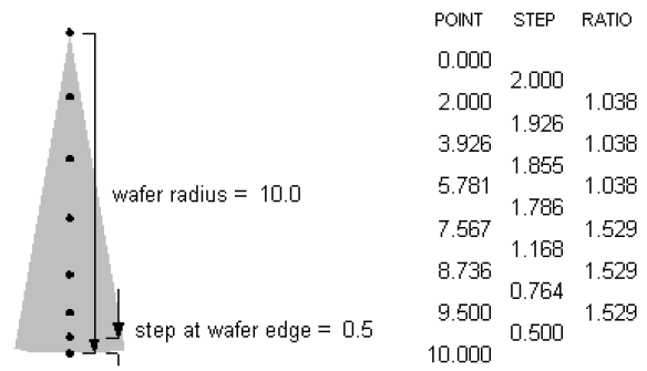
The wafer radius and three parameters determine the radial grid. The LPCVD Furnace Model places one point at the wafers’ edge and one at the wafers’ center. The MAXIMUM RADIAL STEP is the largest step size to be used in the radial direction. The STEP AT WAFER EDGE is the distance between the edge point and its nearest neighbor. The MAXIMUM RADIAL STEP RATIO limits ratios of distances between adjacent points. For example, for 200 mm wafers and for the default parameters (MAXIMUM RADIAL STEP = 2.0, MAXIMUM RADIAL STEP RATIO = 3.0, STEP AT WAFER EDGE = 0.5) the LPCVD Furnace Model chooses the grid with the eight points in Figure 8.4: Radial grid points for 20 cm diameter wafers chosen with default grid parameters
. As intended,
steps between points range from 2.0 cm at the center down to 0.5 cm at the
edge, and ratios of adjacent steps do not exceed 3.0 cm.
The instruction ANNULAR PROBLEM ONLY allows the LPCVD Furnace Model
to economize by discarding the radial grid entirely. This is useful when
developing new chemistry models, because simulations can be performed rapidly.
With this option, the LPCVD Furnace Model does not address intra-wafer
deposition uniformity.
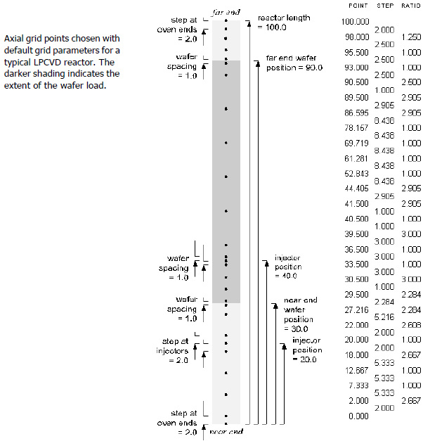
Several keywords control spacing in the axial grid. These are illustrated in Figure 8.5: Axial grid points for a typical LPCVD reactor
, where the dots indicate the positions of the grid points. Separate spacing and ratio limits apply before, after and among the wafers. "Before wafers" means the region between the wafer load and the reactor’s "near end" (small axial position), while "after wafers" means the corresponding region at the reactor’s other end (large axial position). Thus, the MAXIMUM AXIAL STEP BEFORE WAFERS bounds the distance between grid points at one end of the reactor, while the MAXIMUM AXIAL STEP RATIO BEFORE WAFERS bounds the ratios of distances between grid points in that region. Likewise, the MAXIMUM AXIAL STEP AMONG, and AFTER WAFERS can be used to bound the grid spacing among or after the wafer load.
Smaller steps provide better resolution, but with more grid points, they also
require longer computing time.
The LPCVD Furnace Model economizes by using a few grid points to represent several wafers. Along the wafer load, each axial grid point corresponds to a copy of the radial grid that models a typical wafer (and an interwafer region) for a collection of consecutive wafers. This is an acceptable approximation because wafers usually differ little from those nearby. Where more variation is likely (near injectors and at the ends of the wafer load), the LPCVD Furnace Model should be instructed to space axial points more closely. The STEP AT OVEN ENDS specifies the spacing at both reactor
ends.
The LPCVD Furnace Model can be made to model each wafer individually, in two ways. Either the MAXIMUM AXIAL STEP AMONG WAFERS can be set to the WAFER SPACING, or the MAXIMUM AXIAL STEP RATIO AMONG WAFERS can be set to 1.0. In
either case, the number of axial grid points will be at least the number of
wafers, and the LPCVD Furnace Model may need a large amount of memory space and
a long computing time.
The placement of an injector relative to the grid depends on whether it is along or apart from the wafer load.
If an injector lies along the wafer load, its axial position is relocated exactly between wafers, and its radial position is indeterminate in the space between the wafer edges and the reactor wall.
If an injector is positioned away from the wafer load, its axial position is as specified, and its radial position is indeterminate.
There is no accounting for circumferential position because the LPCVD Furnace Model is defined to have axial symmetry. Since the LPCVD Furnace Model assumes uniform gas concentrations within each control volume, injector positions are indeterminate within the enclosing cell. This means deposition predictions are insensitive to small changes in injector position. Injectors must be moved across cell boundaries to alter the predicted deposition rates.
The LPCVD Furnace Model selects its axial grid to fit small cells around injectors. If an injector lies along the wafer load, then the enclosing cell’s width is the WAFER SPACING ; otherwise the width is set to the STEP AT INJECTORS. As an example, if an injector is positioned at 20 cm (not near the wafers), and if the STEP AT INJECTORS is 2 cm (the default), then the axial grid has points at 18, 20 and 22 cm. In contrast, if an injector is nominally positioned at 40 cm somewhere along the wafer load, and if wafers lie at 40 cm with 1 cm spacings, then the LPCVD Furnace Model moves the injector midway between two wafers-in this case to 40.5 cm. (This is done because the LPCVD Furnace Model aligns axial grid points with the gaps between wafers-not with the wafers themselves.) The WAFER SPACING is the grid spacing
at injectors positioned among wafers; for this reason the grid has points at
39.5, 40.5 and 41.5 cm in this case.
If the location of an injector is altered within a pre-defined reactor model, the LPCVD Furnace Model does not re-adjust its grid to reflect the new injector position. Moving an injector may place it in a larger cell where the effect of injected gas is less pronounced because of dilution effects. This change-in-dilution effect can disguise the true effects of changing the injector location. Thus, studies designed to optimize injector placement should use grids with uniformly small spacings.
Several of the keywords for reactor geometry and grid points must be consistent. For example, the MAXIMUM AXIAL STEP BEFORE WAFERS must be
larger than:
the
STEP AT OVEN ENDS,the
WAFER SPACINGand, if an injector lies before the wafers, thenthe
STEP AT INJECTORS.
Problems with grids and dimensions can also be expected when geometric features are particularly close together. For example, the smallest acceptable distance between an end wafer and the reactor end is the STEP AT OVEN ENDS plus half the WAFER SPACING. This minimal configuration is shown on the left side of Figure 8.6: Minimal configuration and normal wafer load for the LPCVD Furnace Model
. The right side of that figure shows the normal case in which the wafer load lies further from the reactor end. In addition, a gas injector can not be placed away from the wafer load but very close to an end wafer. In this case, the closest acceptable spacing is half the WAFER SPACING (which then must match the STEP AT INJECTORS). Usually, it is
best to accept some loss of geometric fidelity by placing such injectors
level with an end wafer (in which case the LPCVD Furnace Model will move
them to the space between that wafer and the next).
