

This tutorial includes:
Important: You must have GT-SUITE installed in order to run this tutorial.
This tutorial was tested to work with GT-SUITE v2019.
In this tutorial you will learn about:
Importing a CCL file to set up a case in CFX-Pre.
Initializing GT-SUITE Coupling.
|
Component |
Feature |
Details |
|---|---|---|
|
CFX-Pre |
User Mode |
General mode |
|
Analysis Type |
Transient | |
|
Fluid Type |
General Fluid | |
|
Domain Type |
Single Domain | |
|
Turbulence Model |
k-Epsilon | |
|
Boundary Conditions |
Opening (GT-SUITE Coupling) |
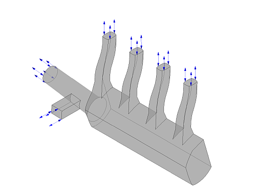
This tutorial models transient flow through a manifold by coupling CFX with GT-SUITE.
The GT-SUITE model is a one-dimensional model of a 4-cylinder engine. The 3D mesh to be coupled is for an intake manifold. The flow consists of a mixture of indolene, nitrogen, oxygen, and combustion products CO2 and water.
The approach to this tutorial is to load a transient simulation from CCL, then couple that simulation with GT-SUITE, exchanging information at the domain boundaries.
Create a working directory.
Ansys CFX uses a working directory as the default location for loading and saving files for a particular session or project.
Copy the following GT-SUITE .gtm file from your GT-SUITE installation into your working directory. Note that the path might not be exactly as shown.
C:\Program Files
                          (x86)\GTI\v2019\tutorials\Co-Simulation_And_UserCode\CFDcoupling\IntakeManifold\CFDCoupling_IntakeManifold.gtm
Download the
intake_manifold_GT.zipfile here .Unzip
intake_manifold_GT.zipto your working directory.Ensure that the following tutorial input files are in your working directory:
IntakeManifold.mshIntakeManifold.cclCFDCoupling_IntakeManifold.gtm
Set the working directory and start CFX-Pre.
For details, see Setting the Working Directory and Starting Ansys CFX in Stand-alone Mode.
The tutorial follows this general workflow for setting up the case in CFX-Pre:
In CFX-Pre, select File > New Case.
Ensure that General is selected and click .
Select File > Save Case As.
Under File name, type
IntakeManifold.Click .
Select File > Import > Mesh.
The Import Mesh dialog box appears.
Under Files of type, select
FLUENT (*cas *msh).From your working directory, select
IntakeManifold.msh.Click Open.
CFX Command Language (CCL) consists of commands used to carry out actions in
CFX-Pre, CFX-Solver Manager, and CFD-Post. The flow analysis settings as well as the
materials required for the simulation will be imported from the CCL file. You
will review, then import, the contents of the
IntakeManifold.ccl file.
Note: The physics for a simulation can be saved to a CCL (CFX Command Language) file at any time by selecting File > Export > CCL.
Open
IntakeManifold.cclwith a text editor and take the time to look at the information it contains.The CCL sets up the following materials:
GT Mixtureindolene combustindolene vaplump N2n2 vapo2 EGRo2 backflowo2 vapprod co2prod h2o
In CFX-Pre, select File > Import > CCL.
The Import CCL dialog box appears.
Under Import Method, select Append. This option appends the changes to the existing case.
Note: The Replace option is useful if you have defined the physics and want to update or replace the existing physics using the newly imported CCL.
From your working directory, select
IntakeManifold.ccl.Click Open.
The CCL is loaded as indicated by the status bar in the bottom right corner of the window. After a short pause, the CCL and the Outline tree view are updated.
In the Outline tree view, expand the
Materialsbranch underSimulationto confirm that new objects have been added after importing the CCL file.
Select Tools > Initialize GT-SUITE Coupling.
The Initialize GT-SUITE Coupling dialog box appears.
Ensure that Create new GT-SUITE model is selected.
Beside Model File, click Browse
 .
.The Select GT-SUITE File dialog box appears.
Select CFDCoupling_IntakeManifold.gtm and click Open.
Optionally, select Specify GT-SUITE Installation and specify the installation directory.
If you do not select this option, the default installation directory will be used.
Click Read Setup From File.
The GT-SUITE coupling information is loaded, and additional options appear for further configuration.
On the Boundary Association tab, ensure that Option is set to
Specify Boundary Names.With this option, GT-SUITE interfaces are mapped to CFX boundaries according to the CFX boundary names in the CFX Boundary column of the two-column mapping table.
Ensure that Allow new boundary names and Create missing boundaries are selected.
Together, these settings automatically create any non-existent mapped boundaries, giving them the specified names. In this case, six boundaries will be created.
On the Material Association tab, ensure that Option is set to
Specify Component Names.This option allows you to manually specify component names to map from GT-SUITE materials to CFX materials. In this case, the mapping requires no adjustments.
On the Function Names tab, ensure that all six GT-SUITE patches are listed under GT-SUITE Interface or Turboshaft Name, with a corresponding GT-SUITE Patch function name listed under CFX Function Name.
The listed GT-SUITE Patch functions will be created. These functions are used to exchange data between CFX boundaries and the corresponding GT-SUITE patches.
Click OK.
GT-SUITE initialization is carried out, resulting in the creation of a GT-SUITE model, several GT-SUITE Patch functions, and boundaries, all of which appear in the Outline tree view.
The coupled boundaries have been created but require location information.
In the Outline tree view, right-click
Simulation>Flow Analysis 1>Default Domain>Cyl 1and select Edit.Configure the following setting(s):
Tab
Setting
Value
Basic Settings
Location
outlet cyl 1
Click .
In a similar way, edit each of the other boundaries to specify a location as shown below.
Boundary
Location
Cyl 2outlet cyl 2
Cyl 3outlet cyl 3
Cyl 4outlet cyl 4
EGRinlet egr
Intakeinlet air
Click Define Run
 .
.Configure the following setting(s):
Setting
Value
File name
IntakeManifold.def
Click .
The CFX-Solver input file (
IntakeManifold.def) is created. CFX-Solver Manager automatically starts and, on the Define Run dialog box, Solver Input File is set.When you are finished, select File > Quit in CFX-Pre.
Click Save & Quit if prompted, to save
IntakeManifold.cfx.
You will now generate a solution for the coupled simulation that you just prepared.
At this point, CFX-Solver Manager is running, and the Define Run dialog box is displayed, with the CFX-Solver input file set.
Click Start Run.
Select the check box next to Post-Process Results when the completion message appears at the end of the run.
If using stand-alone mode, select the check box next to Shut down CFX-Solver Manager.
Click .
Postprocessing is left as a further exercise.