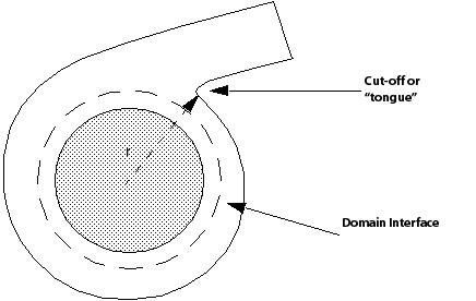
A basic impeller/volute sketch is shown in Figure 11.3: Impeller/Volute. The edge of the inner circle shows the maximum extent of the impeller blades. A good practice here is to create the domain interface halfway across the narrowest gap between the blade and volute wall. This usually occurs around the cut-off or "tongue" illustrated in the diagram.