


You can define a user line cloud, which consists of a field of lines and points along those lines. The lines start at a specified wall boundary and run normal to the wall boundary (except at wall boundary edges, where the boundary normal is not well defined; see below).
A user line cloud can be used to apply field data, such as temperature, a short distance away from where it is sampled. For example, when modeling wall boiling, the temperature near a wall can be applied at the wall in order to compute the boundary layer liquid temperature. For each line in the line cloud, the temperature at each point along the line is sampled and then used to calculate a representative temperature value for the line, which is then applied in the vicinity of the line, within a radius of influence, via an object (for example, the lineCloudAve function) that references the line cloud.
Creating a User Line Cloud
Select Insert > User Locations > User Line Cloud.
The Insert User Line Cloud dialog box appears.
Set Name to a unique name for the user line cloud and click OK.
The details view for the user line cloud appears.
Configure the Boundary Line Location and Boundary Line Type settings.
In the Boundary Line Location settings, Option can be set to:
All WallsThe line cloud is generated over all walls in all domains.
Boundary ListThe line cloud is generated over the boundaries specified by Boundary List.
In the Boundary Line Location settings, optionally select Line Origin Mesh Location and set Location to one of the following:
Face Center
Face Integration Points
Vertex
In the Boundary Line Type settings, Option can be set to:
Fixed LengthSpecify the value for Line Length to be used by every line in the line cloud.
In the Boundary Line Type settings, optionally select Local to Domain to cause lines to terminate on domain boundaries; line points outside domain boundaries are effectively deleted. If Local To Domain is not selected then lines can span domains.
In the Boundary Line Type settings, optionally select Line Influence Radius to Active Length Ratio and specify a value for Ratio. If Line Influence Radius to Active Length Ratio is not selected then the default ratio of 0.1 takes effect. A larger ratio increases the radius of influence of a given line, affecting more of the surrounding field values. Note that the radius of influence of a given line is directed normal to (not parallel to) the line.
In the Boundary Line Type settings, Line Point Distribution > Option can be set to:
UniformThe points along each line are evenly spaced.
Specify a value for Line Point Distribution > Number of Points to specify the number of points per line in the line cloud.
Optionally configure the Line Averaging settings. These settings control how variables are line averaged, offering such control on a per variable basis.
Start by creating a new Line Averaging list item, using the Add new item
 icon to the right of the list.
If you select Line Averaging Distance Fraction, then you can specify, as a value between 0.0 and 1.0, the fraction of the line length over which data is averaged. For example, if you specify a value of 0.25, then only the first quarter of each line, starting at the wall end, is used to compute the variable averages.
If you do not select Line Averaging Distance Fraction, then a value of 1.0 takes effect.
If you select Line Variables List then you can make the averaging settings (currently only Line Averaging Distance Fraction) variable-specific.
Optionally configure the Line Interpolation settings. These settings control how the calculated line cloud values (line averages) are interpolated to the mesh vertices, offering some control on a per variable basis. The mesh vertices just referenced are those that are found within the space occupied by the line cloud.
Optionally select Number of Nearest Interpolation Points and set Value to the number of line cloud values (not necessarily unique values) to use in the interpolation. For each mesh vertex to which values are to be interpolated, a number of nearby line cloud points are used to identify candidate lines. Of those lines, the specified number (Number of Nearest Interpolation Points > Value) are selected in order of nearest line origin. The same line can be selected more than once if more than one line cloud point that is near the mesh vertex belongs to the same line.
Optionally select Cloud Point Distance Tolerance, which is the distance (1E-6 m by default) within which a line point is considered to be coincident with a mesh vertex. If a line point is considered to be coincident with a mesh vertex, the line point value is directly assigned to the mesh vertex (bypassing the rest of the interpolation process for that mesh vertex).
Optionally select Variable Interpolation Distance Weighting to control the weighting for line cloud values in the interpolation process. The weighting for a particular line can be based on the distance from the mesh vertex to the nearest point on the line (
Point Distance) or based on the distance from that nearest point on the line to the line origin (Origin Distance). The weighting is inversely proportional to this distance.Optionally configure the Line Interpolation Variable Options settings. These settings offer per variable control over the weighting used in the interpolation process. Unspecified variables are interpolated as per the Variable Interpolation Distance Weighting specification (mentioned above).
Start by creating a new Line Interpolation Variable Options list item, using the Add new item
icon to the right of the list.Click .
An object named after the user line cloud is created and listed in the tree view under
Simulation>User Locations.
The lines of a line cloud are generally perpendicular to the nearby boundary. Due to discretization error, some lines near boundary edges might not point along the local normal direction. If a boundary includes an edge, for example if two adjacent walls are in the same boundary, then the lines of the line cloud project into the domain using approximately the average of the face normals on either side of the edge.
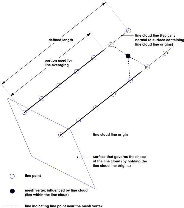
Figure 28.1: Line Cloud Illustration shows two lines of a line cloud and a mesh vertex that is influenced by the three nearest line points.
The process by which a user line cloud generates line averaged values can be summarized as follows:
Field values are interpolated to the line points.
For a given line from a user line cloud:
A piece-wise representation of the line data is constructed using the values at the line points.
The line average is computed by integrating the applicable variable over a length, then dividing by that length, which is the applicable length as determined by Line Averaging Distance Fraction.
The line average value is assigned to the line.
For a given mesh vertex:
Nearby line points are used to identify lines in the line cloud. A selection of these lines have their (line average) values interpolated to the mesh vertex.
The resulting mesh vertex values, which represent line averaged values, are accessible in objects that reference the user line cloud.
To visualize a user line cloud, create a location-based monitor that uses the user line cloud, then, after running the simulation, postprocess the resulting .csv file using CFD-Post.
Note:
User line clouds are not compatible with cases involving:
Mesh deformation
Mesh adaption
Harmonic Analysis
Time Transformation
User line clouds are created at the start of a solver run and are not updated to take account of any changes in the model topology or mesh during the simulation. For example, if a domain interface uses a conditional connection (Conditional Connections in the CFX-Solver Modeling Guide) then the lines are unaffected by the closing of the GGI interface.
User line cloud lines terminate on mesh boundaries; line points outside the mesh are effectively deleted.