Use the Rotation transformation to rotate
an assembly about an axis defined by two points or a principal axis.
This Rotation Option uses the X, Y, or Z axis as the axis of rotation. Select one of the principal axes, under Axis, to be the axis of rotation.
This Rotation Option uses a user-defined axis as the axis of rotation for the transformation. This axis is defined by two Cartesian points, From and To. These points can be entered manually or selected in the viewer by clicking any coordinate box and then clicking in the viewer. The working units are assumed to apply to the point coordinates.
The rotation angle options are Specified, Full Circle, and Two Points.
The Specified option simply rotates the assembly by the specified angle. When looking from the start point to the end point of the axis, a positive angle will produce a rotation in the clockwise direction.
The Full Circle option should be used in conjunction with Multiple Copy, otherwise, the assembly will simply be transformed back to its original position. The effect this has is described more fully in Multiple Copy.
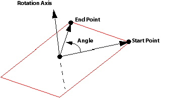
The Two Points option calculates an angle using the axis of rotation and the two points specified, as shown in the following figure. The two points and the start point of the axis define a plane with a normal direction pointing towards the end point of the axis. The angle proceeds in the clockwise direction from the Start to the End point when looking from the start point to the end point of the axis. When picking points from the viewer, the Show Faces render option must be selected to enable a point on a region to be picked. It may also be useful to have Snap to Node selected (on by default in the viewer toolbar).