


Rotating Frames of Reference (RFR) are
useful for rotating fluid machinery applications, such as pump impeller
or turbine blade problems. CFX-Pre enables you to specify a domain
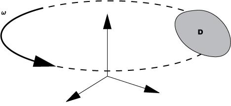
that is rotating about an axis. When you specify a Rotating
Frame of Reference, you must also specify the angular velocity,  , which
can be a function of the built in CEL variable time (
, which
can be a function of the built in CEL variable time (t) in a transient simulation. To determine the direction of the rotation,
use the right-hand rule.
When a domain with a rotating frame is specified, the CFX-Solver computes the appropriate Coriolis and centrifugal momentum terms, and solves a rotating frame total energy equation. Additional mathematical information is available in Rotational Forces in the CFX-Solver Theory Guide.
You can create simulations with multiple reference frames. For details, see Domain Interface Modeling.
Note: For any CCL expression that is defined for a location (such as a domain, boundary, subdomain), coordinates (x, y, z, r, theta) are interpreted in the local frame but variables are normally interpreted in the global frame.
The alternate rotation model is a model for the advection term in the momentum equations. Instead of advecting the relative frame velocity, the flow solver advects the absolute frame velocity.
The main advantage of this model comes into play when the absolute frame velocity is a constant, but the relative frame velocity has a high swirl component. In this case, advecting the relative frame velocity has a high component of error, while advecting a constant absolute frame velocity will have much less error. If the relative and absolute frame velocities are both changing equally, for example, inside a blade passage on a rotating machine, then the alternate rotation model has a similar level of numerical error compared to the default advection model.
The alternate rotation model makes a significant reduction in numerical error when the absolute frame flow is essentially a constant flow parallel to the axis of rotation. For example, the approach flow to a fan or propeller is nearly constant in the absolute frame, but highly rotating flow in the relative frame. At very large radii, small errors in the advection model of the relative frame flow become large errors in the computed flow in the absolute frame. When the alternate rotation model is used in this situation, the numerical error is greatly reduced, because the absolute frame velocity is close to constant. In fact, the numerical error in the advection model reduces to zero as the absolute frame flow becomes axially constant, independent of the radial location and rotation rate.
Conversely, the model can increase errors when, for example, the exit stream is highly swirling. Errors are magnified as the length of the inlet or outlet regions is increased. The choice of whether to apply the model therefore depends on the nature of the inlet and outlet flow conditions, and the length of the inlet and outlet regions.
It has been found that in most realistic flow situations, the
model reduces numerical error (or at least does not increase numerical
error). The one exception is solid body rotation, where the relative
frame flow is constant ( =0) and the absolute frame flow
is nonzero and varying with radius.
=0) and the absolute frame flow
is nonzero and varying with radius.
For more details, see Alternate Rotation Model in the CFX-Solver Theory Guide.