The setup of domain interfaces is an important consideration when defining a turbomachinery problem. The following section outlines some approved practices for use in turbomachinery applications.
Domain Interfaces should typically be placed midway between the rotor and stator for turbomachinery cases.
Where circular domain interfaces exist, they must be axisymmetric in shape.
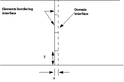
The aspect ratio of elements on the domain interface should not be greater than 10:1. Figure 5.10: Element Aspect Ratio gives a sketch of the requirement for an element aspect ratio of less than 10 on the domain interface. The element aspect ratio (x/y) should lie in the range 0.1 to 10 to avoid numerical errors.
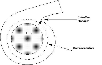
A basic impeller/volute sketch is shown in Figure 5.11: Basic Impeller/Volute. The edge of the inner circle shows the maximum extent of the impeller blades. A good practice here is to create the domain interface halfway across the most narrow gap between the blade and volute wall. This usually occurs around the cut-off or tongue illustrated in the diagram.
For the case shown in Figure 5.12: Step change, there is a step change between the rotor and stator. A common choice for placement of the interface would be choice 1. However, take care with this set-up because the non-overlap regions above and below the interface should be specified as walls. A better alternative may be to use a domain interface upstream or downstream of the step change, at position 2 or position 3.
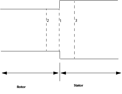
Figure 5.13: Blade extending to the edge of the rotating domain. shows a blade that extends to the edge of the rotating domain. Although it is convenient to place a domain interface at the blade edge (1), this can result in convergence difficulties. A better arrangement is to extend the rotating domain away from the blade edge. Domain Interfaces can then be created at (2), (3), and (4).
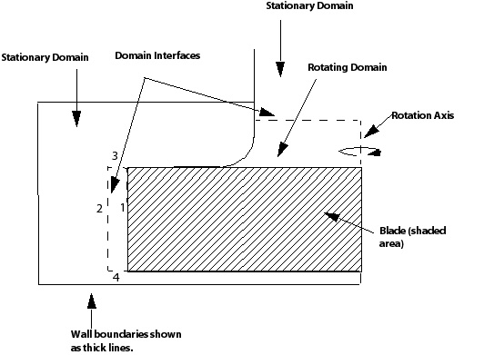
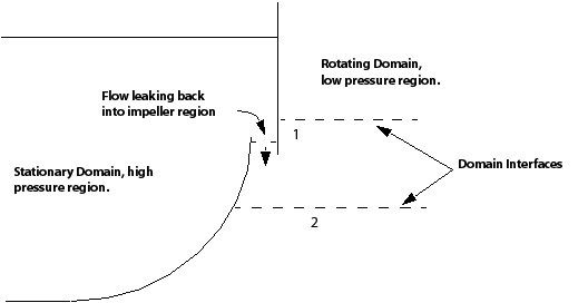
Figure 5.14: Blade passage shows a close-up view of part of Figure 5.13: Blade extending to the edge of the rotating domain., which models flow leaking from a volute back into the impeller region. To model the feature, you can use two domain interfaces (at position 1), or a single domain interface downstream of the leak (position 2).
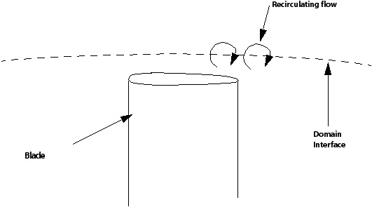
As Figure 5.15: Thick trailing edge shows, when a blade with a thick trailing edge passes close to the domain interface, recirculating flow that crosses the interface can occur. Running a case like this with a Stage interface can produce unphysical results. It is recommended that you either move the domain interface away from possible recirculation zones, or run with the Frozen Rotor interface.