


The button
on the Initialization object can be used to calculate
velocity component (and other) variables pertinent to turbo simulations.
These variables are listed in Table 15.1: Generated Variables and illustrated in Figure 15.6: Axial, Radial, Circumferential, and Meridional Velocity Components, Figure 15.7: Velocity Components in Meridional Plane, Figure 15.8: Streamwise, Spanwise, Circumferential, and Blade-to-Blade Velocity
Components, Figure 15.9: Velocity Components in Blade-To-Blade Plane, and Figure 15.10: Velocity Flow Angle Sign in Each Quadrant on the Blade-to-Blade
Plane. The relationship between the velocity components is described
in Equation 15–1, Equation 15–2, and Equation 15–3.
Note: To get velocity units for tip speed derived from R and Omega quantities, you can divide
the expression by 1 [rad] to eliminate the angle units from the expression.
For example, use:
tipVel = Radius * omega / 1 [rad]
Table 15.1: Generated Variables
|
Variable Name |
Type |
Description |
|---|---|---|
|
Velocity Axial |
Scalar |
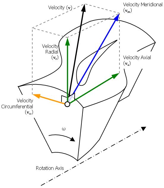
The velocity component in the axial direction. It is positive when the velocity is in the direction of increasing axial coordinate. For details, see Figure 15.6: Axial, Radial, Circumferential, and Meridional Velocity Components and Figure 15.7: Velocity Components in Meridional Plane. |
|
Velocity Radial |
Scalar |
The velocity component in the radial direction. It is positive when the velocity is in the direction of increasing radial coordinate. For details, see Figure 15.6: Axial, Radial, Circumferential, and Meridional Velocity Components and Figure 15.7: Velocity Components in Meridional Plane. |
|
Velocity Circumferential |
Scalar |
The velocity component in the Theta direction. It is positive when the velocity is in the direction of increasing Theta (for details, see Theta). For details, see Figure 15.6: Axial, Radial, Circumferential, and Meridional Velocity Components. |
|
Velocity Spanwise |
Scalar |
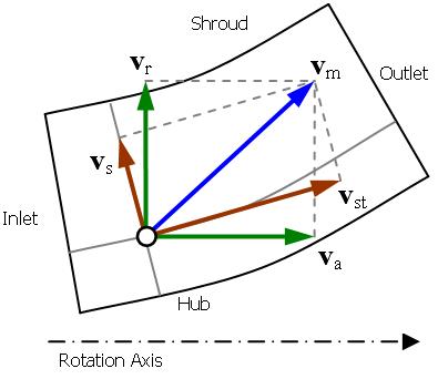
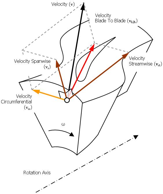
The velocity component in the spanwise direction. It is positive when the velocity is in the direction of increasing spanwise coordinate. For details, see Figure 15.7: Velocity Components in Meridional Plane and Figure 15.8: Streamwise, Spanwise, Circumferential, and Blade-to-Blade Velocity Components. |
|
Velocity Streamwise |
Scalar |
The velocity component in the streamwise direction. It is positive when the velocity is in the direction of increasing streamwise coordinate. For details, see Figure 15.7: Velocity Components in Meridional Plane, Figure 15.8: Streamwise, Spanwise, Circumferential, and Blade-to-Blade Velocity Components, and Figure 15.9: Velocity Components in Blade-To-Blade Plane. |
|
Velocity Meridional |
Vector |
The vector sum of the axial and radial vector components of velocity. It lies in the meridional plane. For details, see Figure 15.6: Axial, Radial, Circumferential, and Meridional Velocity Components, Figure 15.7: Velocity Components in Meridional Plane, and Equation 15–1. |
|
Velocity Blade-to-Blade |
Vector |
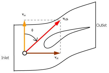
The vector sum of the circumferential and streamwise vector components of velocity. It lies in the blade-to-blade plane. For details, see Figure 15.8: Streamwise, Spanwise, Circumferential, and Blade-to-Blade Velocity Components, Figure 15.9: Velocity Components in Blade-To-Blade Plane, Figure 15.10: Velocity Flow Angle Sign in Each Quadrant on the Blade-to-Blade Plane, and Equation 15–2. |
|
Velocity Flow Angle |
Scalar |
The angle between the blade-to-blade and circumferential velocity vector components. For details, see Figure 15.10: Velocity Flow Angle Sign in Each Quadrant on the Blade-to-Blade Plane. |
The velocity in the meridional plane can be represented by axial and radial components or streamwise and spanwise components:
 | (15–1) |
The velocity in the blade-to-blade plane can be represented by streamwise and circumferential components:
 | (15–2) |
The velocity components are related as follows:
 | (15–3) |
Axial, radial and meridional velocities are not calculated for Velocity in Stn. Frame because these components are not different from the regular Velocity components.
Information on calculating velocity components using CCL is available. For details, see Calculating Velocity Components.
The range of Velocity Flow Angle is from -180° to +180°. Four examples are shown in Figure 15.10: Velocity Flow Angle Sign in Each Quadrant on the Blade-to-Blade Plane.
