


We assume that there is no rotation between a pulley and its axle, but the rope tends to slip over the pulley sheave surface with a friction effect.
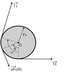
As shown in Figure 9.1: Pulley with Sheave Surface Sliding Friction , a pulley system in an equilibrium
state is acted upon by two end tension forces , where no inertia force
on the pulley is considered.
, where no inertia force
on the pulley is considered.
Considering the pulley system in an equilibrium state, the total force and moment about the pulley axle center must be zero.
We assume that tension variation over the pulley sheave surface obeys the following form
 | (9–2) |
where  is the average sliding friction coefficient along
the rope attachment section.
is the average sliding friction coefficient along
the rope attachment section.
Denoting the radius of the sheave as  and the friction force over a pulley sheave surface
segment
and the friction force over a pulley sheave surface
segment  as
as  , the friction force ensuring a load balance across
this segment is
, the friction force ensuring a load balance across
this segment is
 | (9–3) |
By integrating over the whole attached pulley sheave surface, the total friction force is:
 | (9–4) |
where the total friction force components along the  inline and normal directions are

If the tension ratio  is defined as an input pulley property when
  , the friction factor
  can be evaluated from Equation 9–2 as
 | (9–5) |
Based on the above equations, the reaction force and pulley line end tensions on a pulley system can be evaluated, as long as the attachment points and pulley axle center location are known at the current time step or iteration stage.