


Aqwa calculates the shear force and bending moment distribution of a free-floating structure along a specified neutral axis parallel to either the X-, Y-, or Z-axis of the fixed reference axes (FRA).
As an example, assume that the shear force and bending moment distribution along a neutral
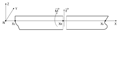
axis parallel to the fixed reference X-axis is required when the structure is at its equilibrium
position. As shown in Figure 14.2: Bending Moment and Shear Force Distribution Along a Neutral Axis, the axis system, NXYZ, is defined
where the X-axis is the neutral axis, and the Y- and Z-axes are parallel to the fixed reference
Y- and Z-axes respectively. The mass distribution is defined from stern  to bow
  ; for a cross-section normal to the neutral axis, the intersection point between
this cross-section and the neutral axis is located at
; for a cross-section normal to the neutral axis, the intersection point between
this cross-section and the neutral axis is located at  (where
  ) in the NXYZ frame.
The external hydrodynamic force and moment with respect to the neutral axis are
 | (14–9) |
where ω is the wave frequency,  is the wetted surface partition from the stern to the cross-section,
 is the summation of the hydrostatic and total hydrodynamic pressures
(consisting of the incident wave, diffraction wave, radiation wave, and the hydrostatic varying
pressures), and
is the summation of the hydrostatic and total hydrodynamic pressures
(consisting of the incident wave, diffraction wave, radiation wave, and the hydrostatic varying
pressures), and  is the normal vector of the wetted hull surface pointing towards the fluid
field. The bending moment acts about the intersection point
is the normal vector of the wetted hull surface pointing towards the fluid
field. The bending moment acts about the intersection point  .
.
If the linearized drag forces/moments with respect to the intersection point  on tube and disc elements are included, the drag force/moment expression given
by Equation 6–20 can be used. However, the relative location vector
defined by Equation 6–18 should be changed to
on tube and disc elements are included, the drag force/moment expression given
by Equation 6–20 can be used. However, the relative location vector
defined by Equation 6–18 should be changed to
 | (14–10) |
The linearized drag force/moment contribution to the shear force and bending moment at the
intersection point  is the summation over all tube/disc elements in the range of
  .
.
The gravitational force and moment with respect to the intersection point  are represented as
 | (14–11) |
where  is the rotational motion response and
  are the mass and geometric center of the j-th section between
  , respectively.
The inertia force and moment with respect to the intersection point  are
are
 | (14–12) |
where  is the motion response at the center of mass of the j-th section and
  is the moment of inertia matrix of the j-th
section.
is the moment of inertia matrix of the j-th
section.
The summations of the corresponding static components in Equation 14–9 and Equation 14–11, which consist of the hydrostatic and gravitational force/moment components only, are referred to as the hydrostatic shear force and bending moments. The summations of all other corresponding components in Equation 14–9 through Equation 14–12 are the dynamic shear force and bending moments.
The maximum value of the shear force/bending moment RAO amplitudes among all of the calculated wave frequency points at a specified section is named as the shear force/bending moment RAO envelope at that section.
If the shear force and bending moment distribution is required along a neutral axis parallel to either the fixed reference Y- or Z-axis, the integration and summation involved in Equation 14–9 through Equation 14–12 should simply be performed in the Y- or Z-direction.