


Most energy at the ocean surface is contributed by wind generated waves, which usually result from the wind blowing over a vast expanse of fluid surface. A wind sea is the wind induced wave system which is directly being generated and affected by the local winds, while a swell consists of wind generated waves that are hardly affected by the local wind at that time but have been generated elsewhere or some time ago. Full-development sea waves are in a state where the largest of the waves in the sea cannot grow any larger and its wave height and wavelength have reached the full potential.
In practice, the linear theory is used to express the multi-directional sea waves (short crested waves) as the summation of a large number of wave components, for instance:
 | (2–28) |
where  and
and  are the number of wave directions and number of wave components
along each wave direction
are the number of wave directions and number of wave components
along each wave direction  ,
,  is the wave
amplitude,
is the wave
amplitude,  is the wave frequency,
  is the wave
number, and
is the wave
number, and  is the random phase angle of a
wave component
is the random phase angle of a
wave component  .
.
The wave representation for irregular seas can be achieved by specification of wave spectra. Mathematically speaking, the wave spectrum spreads from zero to infinite frequencies. However, examination of the spectrum shows that the wave energy is often concentrated in a relatively narrow band, which determines the actual wave pattern. Employing characteristic, the summation given in Equation 2–28 could numerically consist of a limited number of wave components, starting from a non-zero lower bounded frequency and finishing at a finite-value upper bounded frequency. The selection of these starting and finishing frequencies should ensure that this truncated frequency range covers at least 99% of overall wave energy.
If a wave spectrum,  , is introduced for the m-th sub-directional waves, the wave amplitude
  can be expressed as
 | (2–29) |
Uni-directional waves ( ) are also called long-crested waves, which
propagate along one specified direction only.
) are also called long-crested waves, which
propagate along one specified direction only.
Aqwa can accept formulated wave spectrum, user-defined wave spectrum or import time history of wave elevation, and any combination thereof to describe an irregular sea.
The following wave spectral parameters may be useful:
Significant wave height: 
|
Mean wave period: 
|
Mean zero crossing period: 
|
Peak period: 
|
where  and
and  is the peak frequency (in rad/s) at which
the maximum wave energy occurs.
is the peak frequency (in rad/s) at which
the maximum wave energy occurs.
In Aqwa time domain analysis, the irregular waves in the
m-th sub-direction are represented by the wavelets (in other words, wave
components) with constant wave amplitude. Denoting the significant wave height in this
sub-direction as  , from Equation 2–29 the constant wavelet amplitude
is
, from Equation 2–29 the constant wavelet amplitude
is
 | (2–30) |
where Nm is the number of wavelets introduced in Equation 2–28.
There are several pre-configured wave spectra that only require knowledge of a couple of statistical parameters to fully define the sea state. These are explained below.
The JONSWAP (Joint North Sea Wave Project) spectrum can take
into account the imbalance of energy flow in the wave system (for
instance, when seas are not fully developed). Energy imbalance is
nearly always the case when there is a high wind speed. Parameterization
of the classic form of the JONSWAP spectrum (using fetch and wind
speed) was undertaken by Houmb and Overvik [17]. The peak frequency as well as empirical
parameters  and
and  are used in this formulation. The spectral
ordinate at a frequency is given by
are used in this formulation. The spectral
ordinate at a frequency is given by
 | (2–31) |
where
 is the peak frequency in rad/s,
  is the peak enhancement
factor,
is the peak enhancement
factor,  is a constant that relates to the wind
speed and the peak frequency of wave spectrum, and
is a constant that relates to the wind
speed and the peak frequency of wave spectrum, and

Because  is a constant, the integration of this
spectrum can be expressed as
is a constant, the integration of this
spectrum can be expressed as
 | (2–32) |
Therefore if  ,
,  , and
, and  are known, then the variable
  can be determined by
 | (2–33) |
You can define the starting and finishing frequencies of the JONSWAP spectrum used in Equation 2–31. By default, Aqwa gives the definitions as:
Starting frequency (in rad/s):
 | (2–34) |
Finishing frequency (in rad/s):
 | (2–35) |
where the weighting function values against  are listed
in Table 2.1: Weighting Function Values.
are listed
in Table 2.1: Weighting Function Values.
Table 2.1: Weighting Function Values

|

|

|

|

|

|
|---|---|---|---|---|---|
| 1.0 | 5.1101 | 8.0 | 3.3700 | 15.0 | 2.9650 |
| 2.0 | 4.4501 | 9.0 | 3.2900 | 16.0 | 2.9300 |
| 3.0 | 4.1000 | 10.0 | 3.2200 | 17.0 | 2.8950 |
| 4.0 | 3.8700 | 11.0 | 3.1600 | 18.0 | 2.8600 |
| 5.0 | 3.7000 | 12.0 | 3.1050 | 19.0 | 2.8300 |
| 6.0 | 3.5700 | 13.0 | 3.0550 | 20.0 | 2.8000 |
| 7.0 | 3.4600 | 14.0 | 3.0100 |
The Pierson-Moskowitz spectrum is a special case for a fully developed long crested sea. In Aqwa, the Pierson-Moskowitz spectrum is formulated in terms of two parameters of the significant wave height and the average (mean zero-crossing) wave period. The form used in Aqwa is considered of more direct use than the classic form (in terms of the single parameter wind speed), and the form involving the peak frequency (where the spectral energy is a maximum). For more information, see [15]. The spectral ordinate at a frequency (in rad/s) is given by
 | (2–36) |
The following relationship exists between  ,
,  , and
, and  :
:
 | (2–37) |
where  is the mean wave period and
  is the peak period.
You can define the starting and finishing frequencies of the Pierson-Moskowitz spectrum used in Equation 2–36. By default, Aqwa gives the definitions as:
Starting frequency (in rad/s):
 | (2–38) |
Finishing frequency (in rad/s):
 | (2–39) |
The standard Gaussian spectrum is:
 | (2–40) |
where  is the peak frequency (in rad/s),
  is the standard deviation
and
is the standard deviation
and  .
.
You can define the starting and finishing frequencies of the Gaussian spectrum used in Equation 2–40. By default, Aqwa gives the definitions as:
Starting frequency (in rad/s):
 | (2–41) |
Finishing frequency (in rad/s):
 | (2–42) |
If  , they are alternatively
defined as
, they are alternatively
defined as
 | (2–43) |
Ochi-Hubble bimodal spectrum represents almost all stages of the sea condition associated with storm (Ochi and Hubble, 1976 [33]). The spectrum is expressed by the sum of two sets of three-parameter spectra, to cover the lower frequency and high components of the wave energy respectively.
 | (2–44) |
where  is the significant wave height,
  is the spectral shape parameter and
  is the modal frequency in rad/s of the j-th sub-spectrum, and
 is the Gamma function.
The total significant wave height of the Ochi-Hubble spectrum is
 | (2–45) |
Bretschneider spectrum is the special case of the Ochi-Hubble spectrum when
 and j=1. It is expressed by two parameters of significant wave height and
modal frequency,
and j=1. It is expressed by two parameters of significant wave height and
modal frequency,
 | (2–46) |
The zero-crossing frequency (ITTC, 2002 [20]) is
 | (2–47) |
Finite water depth TMA spectrum for non-breaking waves is given as the JONSAWP spectrum multiplying a water depth function (ITTC, 2002 [20]),
 | (2–48) |
where the depth function  , k is the wave number derived from the
linear dispersion relationship of Equation 2–3; the approximately
expression (ITTC, 2002 [20]) of
, k is the wave number derived from the
linear dispersion relationship of Equation 2–3; the approximately
expression (ITTC, 2002 [20]) of  is
is
 | (2–49) |
where  , d is the water depth and


You can input any other spectrum into Aqwa. User-defined wave spectra are normally employed for input of non-deterministic spectra such as tank spectra, recorded full-scale spectra, or simply where the formulated spectrum is not yet available in Aqwa.
The values of frequencies (in rad/s by default) and the values of the spectral ordinates can also be defined.
Aqwa can import a time history series of wave elevation in order to reproduce model test wave conditions.
In an Aqwa time domain analysis (Aqwa-Drift or Aqwa-Naut analysis), the wave elevation time-history will be reproduced exactly, within the frequency range of the fitted spectrum and subject to the limitations of round-off error. This is achieved by multiplying each of the spectral wave components (as in standard Aqwa) by a different low frequency perturbation (LFP) function:
 | (2–50) |
where  is the number of wave components,
  is the wave amplitude,
  is the frequency,
  is the wave number,
  is the phase angle of wave component
  ,
,  where
where  is the wave direction, and
  is the low frequency perturbation
(LFP) function automatically estimated by Aqwa based on the imported
time history record. The starting and finishing wave frequencies are
defined by Equation 2–34 and Equation 2–35, and the amplitude of a wave component
is defined as
is the low frequency perturbation
(LFP) function automatically estimated by Aqwa based on the imported
time history record. The starting and finishing wave frequencies are
defined by Equation 2–34 and Equation 2–35, and the amplitude of a wave component
is defined as  where
where  is the fitted JONSWAP
wave spectral ordinate and
is the fitted JONSWAP
wave spectral ordinate and  is the frequency band of the j-th wave component.
No spurious low frequency waves are generated
by the above method. For any wave component, the minimum frequency
present in the wave elevation is  , where
  is the highest frequency present in the LFP function.
Note also that there is no frequency overlap for each wave component.
Each LFP function can be considered as a frequency spreading function
over a limited set of contiguous frequency bands.
is the highest frequency present in the LFP function.
Note also that there is no frequency overlap for each wave component.
Each LFP function can be considered as a frequency spreading function
over a limited set of contiguous frequency bands.
The minimum duration of the time history required by the program is 7200s (2 hours). This duration is necessary in order to give sufficient resolution of low frequency resonant responses. You may encounter situations where model tests cannot be performed to cover the 2-hour duration. In such cases, Aqwa will extend the imported wave elevation time history record to 7200 seconds by the following approach.
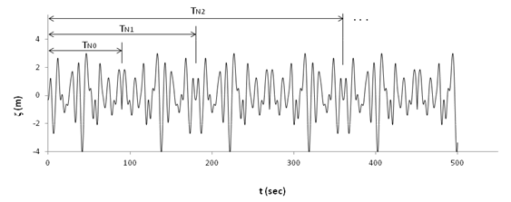
As shown in Figure 2.2: Extension of Wave Elevation Record, if the original
length of time history of wave elevation is assumed to be  , it will be first extended to
  by
by
 | (2–51) |
where  is the number of time steps of the original imported time history
records.
is the number of time steps of the original imported time history
records.
If  after the extension treatment by Equation 2–51, further extension of
  wave elevation points
will be done by using Equation 2–51 again but
replacing the parameters
wave elevation points
will be done by using Equation 2–51 again but
replacing the parameters  and
and  by
by  and
and  respectively. The described extension procedure will be iterated
until the last time step reaches 7200 seconds with
respectively. The described extension procedure will be iterated
until the last time step reaches 7200 seconds with  wave elevation points in total.
An end-correction treatment will be carried out to enable the
Fourier transform to be more accurate. Denoting  as the total number of wave elevation points such
that
as the total number of wave elevation points such
that
 | (2–52) |
the wave elevation values at the starting and finishing ends of the record are corrected as
 | (2–53) |
where  and
and  .
.
This end-corrected time series of wave elevations can also be employed to generate a user-defined spectrum by using a Fast Fourier Transform. The frequency range is based on a JONSWAP fit of the wave elevation spectral density. This fitted wave spectrum is used in the same way as a normal user-defined spectrum, and is employed by Aqwa in equilibrium prediction, frequency domain dynamic statistic analysis, and time domain analysis of severe waves. As the phases of the spectral wave components are allocated randomly, the imported wave elevation time history cannot be reproduced exactly in these types of Aqwa analyses.
Aqwa can simulate the effects of cross swell in most types of analyses, with the exception of time history response of severe waves. It can be defined by a JONSWAP, Pierson-Moskowitz, or Gaussian wave spectrum. The default starting and finishing frequencies of the cross swell wave spectrum will be used automatically, which are defined in Equation 2–34 and Equation 2–35 for JONSWAP spectra, Equation 2–38 and Equation 2–39 for Pierson-Moskowitz spectra, and Equation 2–42 and Equation 2–43 for Gaussian spectra.
As the wind over sea surface is turbulent, the induced wave spectrum is often expressed as two-dimensional, of which one dimension corresponds to frequency and the other to wave direction.
For design/analysis purposes representative spectra  should be in the form of:


For more information, see [4].
The mean direction is assumed to be constant for all wave frequencies and the spreading function is of the form
 | (2–55) |
Where  is the power of the wave spreading
function and
is the power of the wave spreading
function and  is selected to ensure that at each frequency, it
is satisfied that
is selected to ensure that at each frequency, it
is satisfied that
 | (2–56) |
Based on this definition, the above equation becomes
 | (2–57) |
which leads to
 | (2–58) |
For the case of  ,
,
 | (2–59) |
When the spreading angle is set to 180
degrees ( ), Equation 2–58 becomes
 | (2–60) |
Selections of the constant factor  are listed in Table 2.2: Weighting Factors with Respect to the Power Number of Spreading
Function.
are listed in Table 2.2: Weighting Factors with Respect to the Power Number of Spreading
Function.
Table 2.2: Weighting Factors with Respect to the Power Number of Spreading Function
| n | 2 | 3 | 4 | 5 | 6 | 7 | 8 | 9 | 10 |

| 2/
| 3/4 | 8/(3 ) ) | 15/16 | 16/(5 ) ) | 35/32 | 128/(35 ) ) | 315/256 | 256/(63 ) ) |
Aqwa employs a Gaussian integral to numerically represent
spreading seas. When an  -point Gaussian integration scheme is used to represent a spreading
sea, the following equations are used:
-point Gaussian integration scheme is used to represent a spreading
sea, the following equations are used:
 | (2–61) |
where  is the wave energy spectrum in the m-th sub-direction.
 | (2–62) |
where  is the Gaussian integration weighting factor between
the standard integration range of [-1, 1] and
is the Gaussian integration weighting factor between
the standard integration range of [-1, 1] and  is the sub-direction corresponding to the m-th standard Gaussian integration point.
For spreading wave functions with a higher power (n>4), the wave
energy is mainly distributed over a narrower direction range centered in the mean direction  . To increase the numerical accuracy of the spreading wave representation, an
effective wave direction range,
. To increase the numerical accuracy of the spreading wave representation, an
effective wave direction range,  , is introduced. Outside this range, the spreading wave energy is
negligible:
, is introduced. Outside this range, the spreading wave energy is
negligible:
 | (2–63) |
where:

|

|
The Gaussian integration is over the effective wave range  instead of the wave spreading direction range of
  . As an example, the effective range is about
  when n = 250 and
  .
.
You may also define spreading seas with user-defined carpet spectra. You can input each of these carpet spectra with each wave spectrum as a series of directions. It is assumed that the directions are in ascending order, as well as the frequencies at which the value of the spectral ordinates are given. Optionally the specification of individual weighting factors for each direction can be defined.
If you do not define weighting factors, the contribution of each directional spectrum is calculated by a simple trapezoidal integral and will add up to unity. The weighting factors are calculated using the following equation:
 | (2–64) |
where m is the direction
sequence number in a carpet spectral definition and  is the total direction range.
In the case of the first or the last direction, the weighting functions are
 | (2–65) |
It is possible to employ a spectral group to define a specified environmental condition by introducing any combination of the above described wave spectra and/or imported wave elevation time history records.
In Aqwa, each cross swell will be considered as one sub-directional
wave spectrum, a spreading sea is represented by  sub-directional spectra (by using an
  -point Gaussian integration scheme). The overall
maximum total number of sub-directional spectra in each spectral group
is specified by the program. Among each wave spectra group, a limited
number of imported wave elevation time history files may be included.
These sub-directional spectral numbers may vary with different Aqwa versions.
For more information, see the Aqwa User's Manual.
-point Gaussian integration scheme). The overall
maximum total number of sub-directional spectra in each spectral group
is specified by the program. Among each wave spectra group, a limited
number of imported wave elevation time history files may be included.
These sub-directional spectral numbers may vary with different Aqwa versions.
For more information, see the Aqwa User's Manual.
A spectral group may contain only one definition of wind and/or current.