


Theoretically predicting current and wind loads on three dimensional
marine structures with sufficient accuracy is difficult. However,
when the Reynolds number  (in which
  is the characteristic free-stream
velocity and
is the characteristic free-stream
velocity and  is the characteristic length of a prototype marine
structure) is relatively high (for example, it is in the order of
107 for a full scale semi-submersible with diameter 15m, current flow
velocity of 1m/s or wind speed of 40m/s, see [15]), the current or wind forces in the current
or wind direction on the structure can be approximately expressed
in the form of
is the characteristic length of a prototype marine
structure) is relatively high (for example, it is in the order of
107 for a full scale semi-submersible with diameter 15m, current flow
velocity of 1m/s or wind speed of 40m/s, see [15]), the current or wind forces in the current
or wind direction on the structure can be approximately expressed
in the form of
 | (7–1) |
where  is the current or wind drag coefficient and
  is the relative current or wind
velocity in the current or wind travelling direction.
is the relative current or wind
velocity in the current or wind travelling direction.
The hull drag force and moment are normally the functions of
the relative heading angle between the current or wind propagating
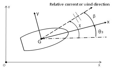
direction and the investigated structure, which can be defined by  , where
  is the current or wind directional
angle in the global fixed frame and
is the current or wind directional
angle in the global fixed frame and  is the yaw angle of the structure, as shown in Figure 7.1: Relative Directional Angle Between Current/Wind and Structure.
At a given relative heading, the hull drag force and moment can be more generally written as
 | (7–2) |
where the subscript j (j = 1,3) represents the force components in the local structure x, y and z directions respectively, the subscript j (j = 4,6) indicates the moment components about the local structure x, y and z directions respectively.
According to the above definition, the coefficients are dimensional so you must conform to a consistent set of units.
The relative wind or current velocity in the above expression is calculated to be the relative velocity between the wind or current velocity and the structure motion velocity along the wind/current direction. In reality, the time scale of the mean wind and current flow is much longer than the typical wave periods, so the wind and current flows do not have time to develop in response to the wave frequency variations of position. In Aqwa, an option can be used to employ the slow velocity (drift frequency velocity) for the hull drag calculation, instead of the total velocity (drift frequency velocity plus wave frequency velocity).
For a floating structure system the relative heading angle may vary at each time step, hence the hull drag coefficients at such headings are required. In order to efficiently evaluate the hull drag force and moment, Aqwa requires the user to define the wind and current hull drag coefficients for a range of relative heading angles. This creates a database which is then accessed during the analysis to interpolate the coefficients at any specified relative heading angle at each time step.
The wind and current drag are both calculated in a similar manner
from a set of user-derived environmental load coefficients, covering
a range of heading angles. Aqwa is based on the potential theory,
so these hull drag coefficients should come from CFD numerical prediction
results, empirical formulas, or model test data. For example, if
under the condition of a known relative heading angle  and known wind or current speed
  , the force and moment about
structure COG in the structure local axis frame,
, the force and moment about
structure COG in the structure local axis frame,  where k=1,6,
are obtained by means of experimental or CFD or empirical approach,
then the drag coefficients at this specific heading angle can be converted
by
where k=1,6,
are obtained by means of experimental or CFD or empirical approach,
then the drag coefficients at this specific heading angle can be converted
by
 | (7–3) |