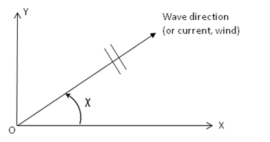
The wave, current and wind directions are defined in the OXY plane of the fixed reference axes (FRA). The direction is defined as the angle between the wave, current, or wind propagating direction and the positive X-axis measured anti-clockwise, as shown in Figure 1.5: Direction Definition. For example, the heading angle is 0 when the wave propagation is along the positive X-axis of the global axes (following wave) and 90 when along the positive Y-axis of the global axes (beam wave).
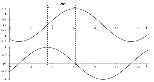
The phase angle of a parameter, such as the surge response amplitude operator (RAO) or wave exciting force, is defined according to the difference from the time when the regular wave crest is at the origin of GXYZ of a structure to the time when this parameter reaches its peak value. In other words, the time histories of an incident wave elevation and a corresponding force or response parameter are represented in the fixed reference axes as
 | (1–10) |
where  is the regular wave amplitude,
  is the wave frequency
(in rad/s),
is the wave frequency
(in rad/s),  is the wave phase angle (in radians) relative
to the origin of the fixed reference axes,
is the wave phase angle (in radians) relative
to the origin of the fixed reference axes,  is the amplitude of the parameter, and
  is the phase angle
of the parameter (in rad/s). The phase angle in degrees is given by:
is the phase angle
of the parameter (in rad/s). The phase angle in degrees is given by:
 | (1–11) |
As shown in Figure 1.6: Phase Definition, a positive phase angle indicates that the parameter lags behind the wave.