


Benchmark C2
VMC2
Elliptic Membrane Under a Uniformly Load
Overview
Test Case
An elliptic membrane structure of thickness t is subjected to a uniformly distributed outward pressure P. Monitor the tangential edge stress σy at target point 1 for a series of uniform mesh refinements using quadrilateral and triangular elements. Compare the effect of increased mesh refinement with the percent energy error norm.

| Material Properties | Geometric Properties | Loading and Boundary Conditions | |||||||||||||
|---|---|---|---|---|---|---|---|---|---|---|---|---|---|---|---|
|
|
|
Results Tables
Target Solution: SY = 92.7 MPa Results Comparison - Quadrilateral and Triangle Meshing
Assumptions, Modeling Notes, and Solution Comments
From an element performance standpoint, the problem is designed to test membrane elements for accurate modeling of the strain variation, nodal stress extrapolation, and curved boundary modeling (of higher order elements).
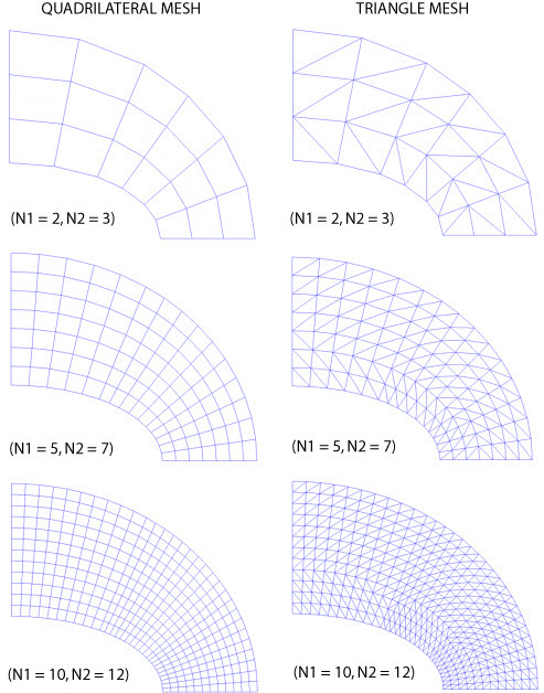
From a modeling standpoint, the problem is designed to test quadrilateral and triangular meshes for solution accuracy with various element types. For the areas modeled, all exterior line segment specifications for mesh density are made equal for the various mesh options.
For quadrilateral and triangle element meshes under uniform mesh refinement (parameters N1 and N2 varied), the calculated percent error in energy norm follows a log-log linear relationship to the number of degrees of freedom in the model. The higher order element (PLANE183) exhibits nearly identical log-log slopes while the lower order element (PLANE182) exhibits a more gradual slope. These results illustrate that the PLANE183 solutions converge at nearly the same rate under uniform refinement while PLANE183 converges at a slower rate. The percent error in energy norm results indicate that global accuracy is best obtained by PLANE82 for any given DOF set. However, the σy stress at target point 1 shows that for uniform refinement, PLANE182 gives better results (at that point) under moderate mesh refinement. A fine mesh using PLANE183 in place of a coarse mesh of PLANE183 may produce better localized stress values.