


Benchmark C1
VMC1
Built-In Plate Under Uniformly Distributed Load
Overview
Test Case
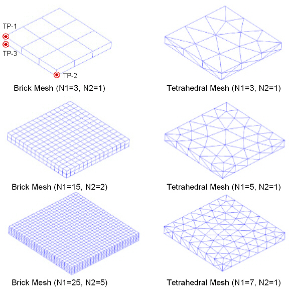
A rectangular plate with built-in edges is subjected to a uniform pressure load on the top and bottom surface. Monitor displacement and stress results at three target points for a series of mesh refinements for different elements. Compare the effect of increased mesh refinement on the percent energy error norm.

| Material Properties | Geometric Properties | Loading and Boundary Conditions for Mechanical APDL Model | ||||||||||||||||||
|---|---|---|---|---|---|---|---|---|---|---|---|---|---|---|---|---|---|---|---|---|
|
|
|
Solution Information
Table 23: Target Solution
| ETYP | N1 | N2 | DOF | % Error Norm | UZ(1), in | SX(2), ksi | SX(3), ksi |
|---|---|---|---|---|---|---|---|
| 95 | 25 | 10 | 45708 | 10 | -.0172 | -32.124 | 14.465 |
Table 24: Results Comparison
| ETYP | N1 | N2 | DOF | % Error Norm | UZ(1)[a] | SX(2)[a] | SX(3)[a] |
|---|---|---|---|---|---|---|---|
|
185 |
3 |
1 |
96 |
56.946 |
0.928 |
0.434 |
0.935 |
|
185 |
6 |
1 |
294 |
34.017 |
0.962 |
0.653 |
0.973 |
|
185 |
15 |
2 |
2304 |
19.154 |
0.980 |
0.850 |
0.991 |
|
185 |
20 |
4 |
6615 |
14.591 |
0.987 |
0.913 |
0.996 |
|
185 |
25 |
5 |
12168 |
13.202 |
0.990 |
0.936 |
0.997 |
|
186 |
3 |
1 |
288 |
8.365 |
0.958 |
0.829 |
1.037 |
|
186 |
6 |
1 |
945 |
7.725 |
0.978 |
0.955 |
1.006 |
|
186 |
15 |
2 |
8160 |
10.250 |
0.991 |
0.961 |
0.999 |
|
186 |
20 |
4 |
24507 |
10.160 |
0.997 |
1.001 |
1.000 |
|
187 |
3 |
1 |
741 |
37.573 |
0.957 |
0.822 |
0.977 |
|
187 |
5 |
1 |
1377 |
27.360 |
0.974 |
0.934 |
1.001 |
|
187 |
6 |
1 |
1917 |
25.354 |
0.977 |
0.949 |
1.000 |
|
187 |
10 |
2 |
4629 |
20.425 |
0.984 |
0.966 |
1.000 |
[a] UZ(1), SX(2), and SX(3) show percentages normalized with Target Solution and have no units.
Table 25: Results Comparison - Shell Element and Analytical Solution
| ETYP | N1 | N2 | DOF | % Error Norm | UZ(1), in | SX(2), ksi | SX(3), ksi |
|---|---|---|---|---|---|---|---|
| 35 | 5 | 1 | 576 | NA | -.0165 | -29.580 | 14.303 |
| Approximate Analytical Solution (neglecting shear deflection) | -.0138 | -30.780 | 13.860 | ||||
Assumptions, Modeling Notes, and Solution Comments
The problem exhibits symmetry about the midplane of the plate, and about the X and Y axes. This symmetry allows for a 1/8 symmetry sector to be modeled.
The approximate analytical solution neglects shear deflection. Shear deflection is accounted for in the finite element solutions.
The target solution is obtained from a fine mesh solution using SOLID186.
The 8-node isoparametric shell (SHELL281), subjected to the same loading, has results in line with the target solution. The SHELL281 element takes into account shear deflection effects.
Deflection and bending stresses converge quickly to the target solution at the center of the plate (target points 1 and 3) for the solid element test cases.
Bending-stresses are maximum at the built-in edges, peaking at the midspan of the plate (target point 2). It can be seen that a significant number of elements through the plate thickness are required to accurately predict the bending stresses at the built-in edge for the solid elements.
The percent error in energy norm remains relatively high as the mesh is refined, with most of the error energy located at the built-in edges. This behavior is expected at built-in edges where point-wise inaccuracies in the solution occur. The displacement and stress results for which the refinement was targeted are quite good, despite the high energy error.