VM90
VM90
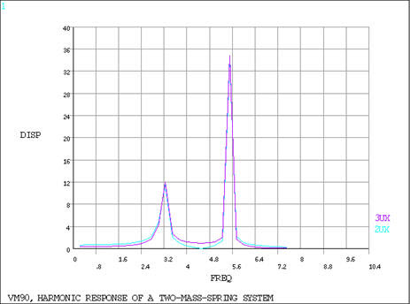
Harmonic Response of a Two-Mass-Spring System
Test Case
Determine the response amplitude (Xi) and phase angle (Φi) for each mass (mi) of the system in Figure 127: Two-Mass-Spring System Problem Sketch when excited by a harmonic force (F1sin ωt) acting on mass m1.

| Material Properties | Loading | |||
|---|---|---|---|---|
|
|
Analysis Assumptions and Modeling Notes
The spring lengths are arbitrarily selected and are used only to define the spring direction. A frequency range from zero to 7.5 Hz with a solution at 7.5/30 = 0.25 Hz intervals is chosen to give an adequate response curve. POST26 is used to get amplitude versus frequency display.
Results Comparison
| Target | Mechanical APDL | Ratio | |
|---|---|---|---|
| X1 , in (f = 1.5 Hz)[1] | 0.82272 | 0.82272 | 1.000 |
| Angle1, deg (f = 1.5 Hz) | 0.0000 | 0.0000 | - |
| X2 , in (f = 1.5 Hz)[1] | 0.46274 | 0.46274 | 1.000 |
| Angle2, deg (f = 1.5 Hz) | 0.000 | 0.0000 | - |
| X1 , in (f = 4.0 Hz) | 0.51145 | 0.51146 | 1.000 |
| Angle1, deg (f = 4.0 Hz) | 180.00 | 180.00 | 1.000 |
| X2 , in (f = 4.0 Hz) | 1.2153 | 1.2153 | 1.000 |
| Angle2, deg (f = 4.0 Hz) | 180.00 | 180.00 | 1.000 |
| X1 , in (f = 6.5 Hz) | 0.58513 | 0.58512 | 1.000 |
| Angle1, deg (f = 6.5 Hz) | 180.00 | 180.00 | 1.000 |
| X2 , in (f = 6.5 Hz) | 0.26966 | 0.26965 | 1.000 |
| Angle2, deg (f = 6.5 Hz) | 0.0000 | 0.0000 | - |