VM44

VM44
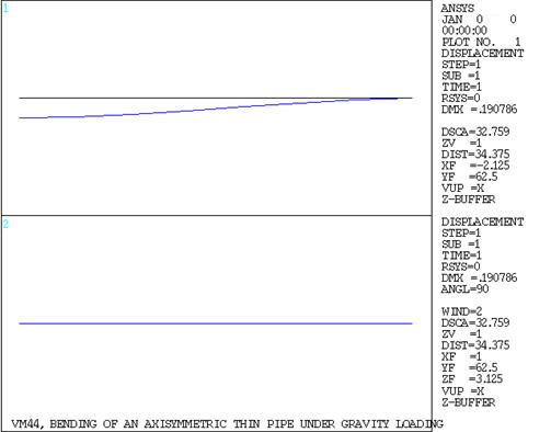
Bending of an Axisymmetric Thin Pipe

Overview

Reference:R. J. Roark, Formulas for Stress and Strain, 4th Edition, McGraw-Hill Book Co., Inc., New York, NY, 1965, pg. 112, no. 33.
Analysis Type(s):Static Analysis (ANTYPE = 0)
Element Type(s):Axisymmetric Harmonic Structural Shell Elements (SHELL61)
Input Listing:vm44.dat

Test Case

A long thin-walled pipe is rigidly supported at its ends between two walls. Determine the maximum deflection in the pipe due to gravity loading. Determine the maximum tensile stress σmax at the outer surface of the pipe at Y = 0.

Figure 60: Axisymmetric Thin Pipe Problem Sketch

Axisymmetric Thin Pipe Problem Sketch

Material PropertiesGeometric PropertiesLoading
E = 30 x 106 psi
ρ = 0.00073 lb-sec2/in4
υ = 0.0
L = 250 in
D = 2 in
t = 0.1 in
g = 386 in/sec2

Analysis Assumptions and Modeling Notes

The loading g, which is constant in magnitude and direction around the circumference of the pipe, is applied as the sum of two harmonically varying loads. Each load has one wave around the circumference and is 90° out of phase with the other.

Results Comparison

TargetMechanical APDLRatio
Deflectionx, in (angle = 0°)-0.19062-0.190791.001
Deflectionz, in (angle = 90°)0.190620.190791.001
Stressmax , psi (angle = 0°)3074.33059.115[1]0.995
  1. Corresponds to S1 at BOT of element 1 (section at node I).

Figure 61: Displacement Displays

Displacement Displays
Window 1 Shows a Circumferential Angle of 0°
Window 2 Shows a Circumferential Angle of 90°