VM39

VM39
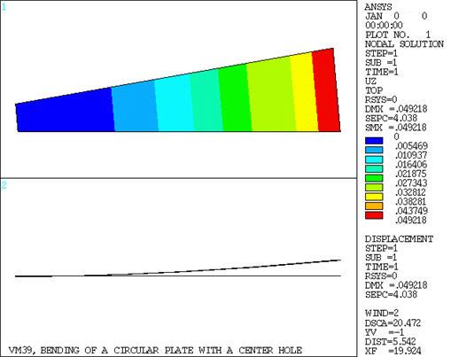
Bending of a Circular Plate with a Center Hole

Overview

Reference:S. Timoshenko, Strength of Material, Part II, Elementary Theory and Problems, 3rd Edition, D. Van Nostrand Co., Inc., New York, NY, 1956, pg. 111, eq. E and F.
Analysis Type(s):Static Analysis (ANTYPE = 0)
Element Type(s):
Elastic Shell Elements (SHELL63)
4-Node Finite Strain Shell Elements (SHELL181)
Input Listing:vm39.dat

Test Case

A circular plate of thickness t with a center hole is rigidly attached along the inner edge and unsupported along the outer edge. The plate is subjected to bending by a moment Ma applied uniformly along the outer edge. Determine the maximum deflection δ and the maximum slope Φ of the plate. In addition, determine the moment M and stress σx at the top centroidal locations of element 1 (near inner edge) and element 6 (near outer edge).

Figure 52: Circular Plate Problem Sketch

Circular Plate Problem Sketch

Material PropertiesGeometric PropertiesLoading
E = 30 x 106 psi
υ = .3
a = 30 in
b = 10 in
t = .25 in
Θ = 105
Ma = 10 in-lb/in
= 52.360 in-lb/10° segment

Analysis Assumptions and Modeling Notes

Since the problem is axisymmetric only a small sector of elements is needed. A small angle Θ = 10° is used for approximating the circular boundary with a straight-edged element. A radial grid with nonuniform (3:1) spacing is used. The calculated load is equally divided and applied to the outer nodes.

The model is first solved using SHELL63 elements and then using SHELL181 elements.

Results Comparison

TargetMechanical APDLRatio
SHELL63
Deflection, in.049064.0492181.003
Slope, rad-.0045089-.00452491.004
@ x = 10.81 in.M, in-lb/in-13.783-13.6750.992
Stressx , psi-1323.2-1312.7320.992
@ x = 27.1 in.M, in-lb/in-10.127-10.1331.001
Stressx , psi-972.22-972.7421.001
SHELL181
Deflection, in.049064.04917801.002
Slope, rad-.0045089-.00452931.005
@ x = 10.81 in.M, in-lb/in-13.783-13.8011.001
Stressx , psi-1323.2-1318.6090.997
@ x = 27.1 in.M, in-lb/in-10.127-10.1661.004
Stressx , psi-972.22-974.9591.003

Figure 53: Window 1: UZ Displacement Contours; Window 2: Displaced Shape - Edge View

Window 1: UZ Displacement Contours; Window 2: Displaced Shape - Edge View