


VM310
VM310
Electrostatic-Structural Analysis of a MEMS Parallel-Plate
Capacitor
Overview
| Reference: | Any basic Electrostatics textbook |
| Analysis Type(s): |
Static Analysis (ANTYPE = 0) Linear Perturbation Static Analysis (ANTYPE = 0) Linear Perturbation Modal Analysis (ANTYPE = 2) Linear Perturbation Harmonic Analysis (ANTYPE = 3) |
| Element Type(s): |
3D 20-Node Coupled-Field Solid (SOLID226) Spring-Damper (COMBIN14) Structural Mass (MASS21) |
| Input Listing: | vm310.dat |
Test Case
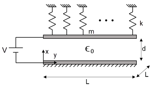
As shown in the problem sketch below, a parallel-plate capacitor consists of two conducting parallel plates of length L at distance d from each other. The lower plate is fixed. The upper plate is attached to a set of mass-springs. The total mass per unit area is m, and the total stiffness per unit area is k. First, a voltage difference V is applied between the plates to determine the displacement of the upper plate caused by the electrostatic force acting between them. Then the model is restarted from a bias voltage (VDC), and a series of linear perturbation analyses are performed to determine the static, modal, and harmonic response of the DC-biased capacitor.
| Material Properties | Geometric Properties | Loading | ||||||||||
|---|---|---|---|---|---|---|---|---|---|---|---|---|
|
Free space permittivity:
Spring constant per unit area:
Plate mass per unit area:
|
Thickness:
Plate length:
|
Static analysis:
Linear perturbation analyses:
|
Analysis Assumptions and Modeling Notes
The space between the electrode plates is modeled using SOLID226 to allow for the deformation of the air region caused by the electrostatic force acting between the electrodes. A negligible elastic modulus is assigned to this region. KEYOPT(4) is set to 1 to avoid applying the electrostatic forces to the interior nodes of the meshed region. The displacement components UY and UZ, which are parallel to the faces of the plates, are all suppressed, and the orthogonal component UX is constrained to be uniform on the top electrode while set to zero on the bottom electrode. The nodes of SOLID226 located on the top electrode are each attached to a spring modeled by spring-damper (COMBIN14). The stiffness of each spring is kA/n where A is the plate area (A = L2) and n is the total number of springs. Similarly, and to account for the mass of the electrode, a point mass mA/n is defined by structural mass (MASS21) at each node residing on the top electrode.
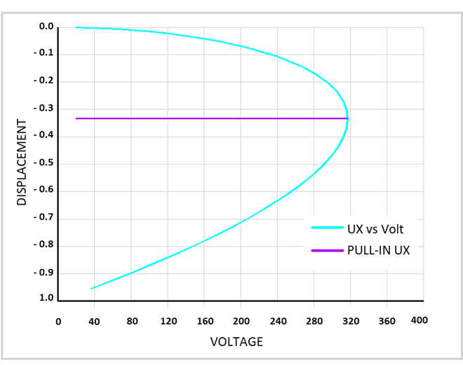
To be able to continue the simulation after reaching the pull-in condition, the applied voltage should be reduced. This is achieved by using the Arc Length Method: The maximum voltage load is set at 500 V. The voltage load is increased up to the pull-in voltage (VPI = 316.85 V), and then it is reduced automatically to maintain equilibrium afterward. The program, therefore, traces the displacement-voltage curve downward to the region where the electrodes meet each other at near zero voltage. The Arc Length Method is activated by the ARCLEN command and is set to terminate when the displacement is 95 percent of the capacitor thickness using the ARCTRM command.
For a given value of displacement, the corresponding value of the voltage is obtained from the analytical solution, and the ratio of numerical and analytical voltages averaged along the displacement-voltage curve is obtained as

where  is the number of substeps.
Results Comparison
Nonlinear Static Analysis:
| Target | Mechanical APDL | Ratio | ||
| Pull-in voltage |

| 316.850 | 317.963 | 1.003512 |
| Pull-in displacement |

| 0.333333 | 0.359038 | 1.077113 |
| Disp-volt curve |

| — | — | 0.999936 |
| Capacitance at VDC |

| 0.955739E-03 | 0.959987E-03 | 1.004445 |
Linear Perturbation Static Analysis:
| Target | Mechanical APDL | Ratio | ||
| Displacement |
where
and
| 0.840715E-02 | 0.845863E-02 | 1.006123 |


Linear Perturbation Modal Analysis (Resonance):
| Target | Mechanical APDL | Ratio | ||
| Frequency |

| 253.029 | 252.818 | 0.999166 |
Linear Perturbation Modal Analysis (Anti-Resonance):
| Target | Mechanical APDL | Ratio | ||
| Frequency |

| 275.664 | 275.664 | 0.999999 |
Linear Perturbation Harmonic Analysis (Actuator Mode):
| Target | Mechanical APDL | Ratio | ||
| Displacement |

| 0.560236E-02 | 0.8460001E-02 | 1.006133 |
Linear Perturbation Harmonic Analysis (Sensor Mode):
| Target | Mechanical APDL | Ratio | ||
| Voltage |

| -11.17560 | -11.22530 | 1.004447 |