


VM263
VM263
Critical Speeds for a Rotor Bearing System with Axisymmetric
Elements
Overview
Test Case
A rotor-bearing system is analyzed to determine the whirl speeds. The distributed rotor was modeled as a configuration of six elements with each element composed of sub elements. See Table 263.1: Geometric data for rotor-bearing elements for a list of data for the elements. Two undamped linear bearings were located at positions four and six. A modal analysis is performed with multiple load steps to determine the critical speeds for the system.
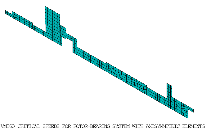
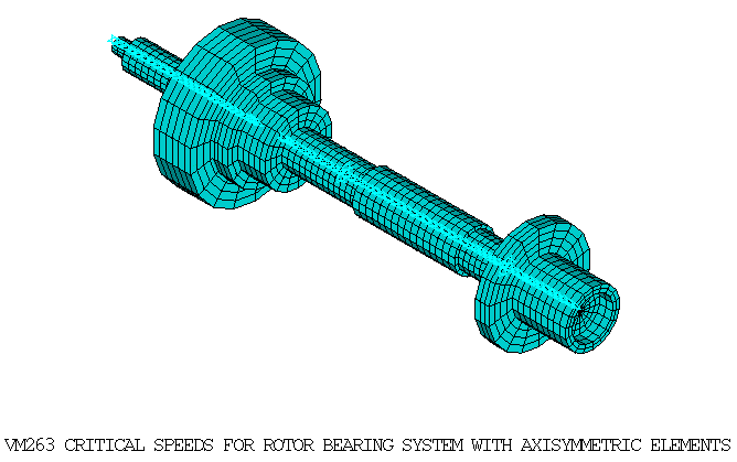
Table 13: Geometric Data of Rotor-Bearing Elements
| Element No. | Subelement No. | Axial Distance to Subelement (cm) | Inner Diameter (cm) | Outer Diameter (cm) |
|---|---|---|---|---|
| 1 | 1 | 0.00 | 0.51 | |
| 2 | 1.27 | 1.02 | ||
| 2 | 1 | 5.08 | 0.76 | |
| 2 | 7.62 | 2.03 | ||
| 3 | 1 | 8.89 | 2.03 | |
| 2 | 10.16 | 3.30 | ||
| 3 | 10.67 | 1.52 | 3.30 | |
| 4 | 11.43 | 1.78 | 2.54 | |
| 5 | 12.70 | 2.54 | ||
| 6 | 13.46 | 1.27 | ||
| 4 | 1 | 16.51 | 1.27 | |
| 2 | 19.05 | 1.52 | ||
| 5 | 1 | 22.86 | 1.52 | |
| 2 | 26.67 | 1.27 | ||
| 6 | 1 | 28.70 | 1.27 | |
| 2 | 30.48 | 3.81 | ||
| 3 | 31.50 | 2.03 | ||
| 4 | 34.54 | 1.52 | 203 |
| Material Properties | Geometric Properties | Loading |
Shaft and Disc: E = 2.078E11 Pa DENS = 7800 Kg/m^3 Nu = 0.3 Bearing stiffness: Kyy = 4.378E+07 N/m Kzz = 4.378E+07 N/m | Shaft: Refer to Table 263.1 Disc: Thickness = 0.0254 m Outer Radius = 0.0495 m Inner Radius = 0.0203 m | Rotational velocity: 1st load step = 0 rpm 2nd load step = 10,000 rpm 3rd load step = 20,000 rpm 4th load step = 40,000 rpm 5th load step = 60,000 rpm 6th load step = 80,000 rpm 7th load step = 100,000 rpm |
Analysis Assumptions and Modeling Notes
Both the shaft and the disc are modeled using SOLID272 and SOLID273 elements with 3 Fourier nodes in the circumferential direction. The thickness, outer radius and inner radius of the disc are adjusted to match the mass and moment of inertia of the mass element used in the reference. Two symmetric bearings along the global Y and Z directions are modeled using COMBIN14 elements.
A modal analysis is performed on the rotor-bearing system with multiple load steps using DAMP eigen-solver to determine the whirl speeds and Campbell values. The translational displacements along X are constrained so that the system does not have axial motion. The gyroscopic effect is activated by turning the CORIOLIS command on in a stationary reference frame. The whirl speeds for slopes (excitation per revolution) 2.0 and 4.0 are determined and compared with analytical solutions.
The problem is also solved using Component Mode Synthesis (CMS) Substructuring modeling approach by creating superelements for the shaft and disc modeled with SOLID272 elements. The gyroscopic damping matrix is generated in the CMS generation pass using the fixed interface method. Campbell analysis is performed using the superelements created in the generation pass along with symmetric bearing elements modeled using COMBIN14 elements in the use pass.
The whirl speeds for slopes (excitation per revolution) 2.0 and 4.0 are determined for all different cases and compared with analytical solutions.
Results Comparison
| General Axisymmetric Solid with 4 Base Nodes SOLID272 | |||
|---|---|---|---|
| Target | Mechanical APDL | Ratio | |
| Whirl Speeds for slope = 2 | |||
| Mode 1 | 7929.000 | 7693.2214 | 1.004 |
| Mode 2 | 8350.000 | 8390.0339 | 1.005 |
| Mode 3 | 23760.000 | 23329.4593 | 0.982 |
| Mode 4 | 24602.000 | 24171.9504 | 0.983 |
| Mode 5 | 34820.000 | 34332.9165 | 0.986 |
| Mode 6 | 42776.000 | 41973.2935 | 0.981 |
| Whirl Speeds for slope = 4 | |||
| Mode 1 | 4015.000 | 4032.8771 | 1.004 |
| Mode 2 | 4120.250 | 4139.5244 | 1.005 |
| Mode 3 | 11989.250 | 11775.7074 | 0.982 |
| Mode 4 | 12200.000 | 11986.2327 | 0.982 |
| Mode 5 | 18184.250 | 17947.6609 | 0.987 |
| Mode 6 | 20162.250 | 19879.7025 | 0.986 |
| General Axisymmetric Solid with 4 Base Nodes SOLID272 and CMS Substructure Analysis | |||
|---|---|---|---|
| Target | Mechanical APDL | Ratio | |
| Whirl Speeds for slope = 2 | |||
| Mode 1 | 7929.000 | 7693.2581 | 1.004 |
| Mode 2 | 8350.000 | 8390.0777 | 1.005 |
| Mode 3 | 23760.000 | 23331.5953 | 0.982 |
| Mode 4 | 24602.000 | 24174.3827 | 0.983 |
| Mode 5 | 34820.000 | 34343.3905 | 0.986 |
| Mode 6 | 42776.000 | 41999.2282 | 0.982 |
| Whirl Speeds for slope = 4 | |||
| Mode 1 | 4015.000 | 4032.8903 | 1.004 |
| Mode 2 | 4120.250 | 4139.5399 | 1.005 |
| Mode 3 | 11989.250 | 11776.7349 | 0.982 |
| Mode 4 | 12200.000 | 11987.3387 | 0.983 |
| Mode 5 | 18184.250 | 17952.1213 | 0.987 |
| Mode 6 | 20162.250 | 19887.0585 | 0.986 |
| General Axisymmetric Solid with 8 Base Nodes SOLID273 | |||
|---|---|---|---|
| Target | Mechanical APDL | Ratio | |
| Whirl Speeds for slope = 2 | |||
| Mode 1 | 7929.000 | 7922.4021 | 0.999 |
| Mode 2 | 8350.000 | 8354.3326 | 1.001 |
| Mode 3 | 23760.000 | 23296.8632 | 0.981 |
| Mode 4 | 24602.000 | 24169.2596 | 0.982 |
| Mode 5 | 34820.000 | 34257.9202 | 0.984 |
| Mode 6 | 42776.000 | 41659.3899 | 0.974 |
| Whirl Speeds for slope = 4 | |||
| Mode 1 | 4015.000 | 4013.0321 | 1.000 |
| Mode 2 | 4120.250 | 4120.9556 | 1.000 |
| Mode 3 | 11989.250 | 11763.2155 | 0.981 |
| Mode 4 | 12200.000 | 11981.2704 | 0.982 |
| Mode 5 | 18184.250 | 17894.3039 | 0.984 |
| Mode 6 | 20162.250 | 19770.4380 | 0.981 |