VM223
VM223
Electro-Thermal Microactuator Analysis
Test Case
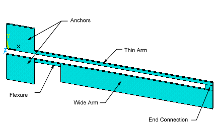
The actuator silicon structure has a thin arm connected to a
wide arm, flexure, and two anchors as shown in the figure below. In
addition to providing mechanical support, the anchors also serve as
electrical and thermal connections. The actuator operates on the principle
of differential thermal expansion between the thin and wide arms.
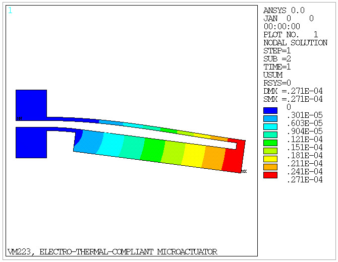
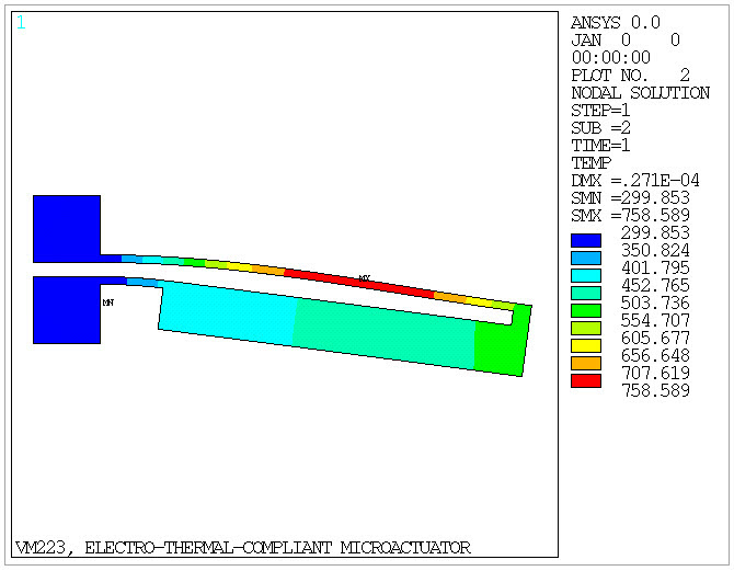
When a voltage difference is applied to the anchors, current flows
through the arms producing Joule heating. Because of the width difference,
the thin arm of the microactuator has a higher electrical resistance
than the wide arm, and therefore it heats up more than the wide arm.
The non-uniform Joule heating produces a non-uniform thermal expansion,
and actuator tip deflection.
Analysis Assumptions and Modeling Notes
A 3D static structural-thermoelectric analysis is performed to determine the tip deflection
and temperature distribution in the microactuator when a 15 volt difference is applied to the
anchors. Radiative and convective surface heat transfers are also taken into account, which is
important for accurate modeling of the actuator.
MPAMOD,1,0 is added to convert the temperature-dependent secant coefficient
of thermal expansion from definition to reference temperature.