VM222

VM222
Warping Torsion Bar

Overview

Reference:C-N Chen, "The Warping Torsion Bar Model of the Differential Quadrature Method", Computers and Structures, Vol. 66 No. 2-3, 1998, pp. 249-257.
Analysis Type(s):Static Structural (ANTYPE = 0)
Element Type(s):
3D Linear Finite Strain Beam Elements (BEAM188)
3D Quadratic Finite Strain Beam Elements (BEAM189)
Input Listing:vm222.dat

Test Case

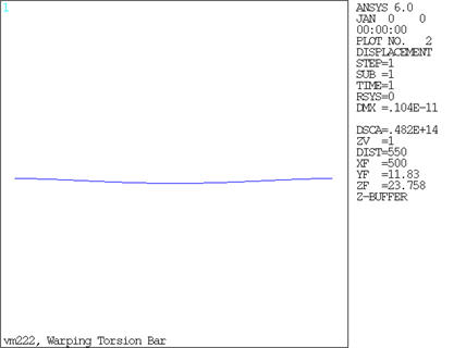
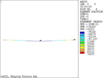
A cantilever I-beam is fixed at both ends and a uniform moment, Mx, is applied along its length.

Figure 365: Warping Torsion Bar Problem Sketch

Warping Torsion Bar Problem Sketch

Material PropertiesGeometric PropertiesLoading
Warping rigidity (ECW) = 7.031467e12 Nmm4 and GJ=3.515734e7 Nmm2
Warping constant (CW) =0.323e8 and J=431.979 (E=217396.3331684 N/mm2 and G=81386.6878 N/mm2)
Poisson's Ratio = (E/(2*G))-1 = 0.33557673
b=40mm
h=80mm
t=2mm
L=1000mm
Moment = 1Nmm/mm

Figure 366: I-Beam Section Plot

I-Beam Section Plot

Analysis Assumptions and Modeling Notes

Given that:

ECw = 7.031467E12 Nmm4(warping rigidity)
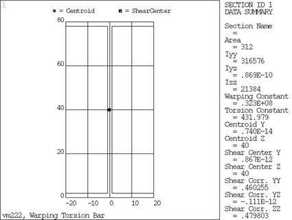
Iyy = 316576 mm4 for this beam cross section

and

GJ = 3.515734E7 Nmm2
Cw = 0.323E8 mm6 (warping constant)
J = 431.979 mm4 (torsion constant)
E = 217396.333 N/mm2 (Young's modulus)

Therefore υ = E/2G-1 = 0.33557673 (Poisson's ratio)

Uniformly distributed moments are converted to a moment load on each element.

mload1 and mload2 are the loads on the beam ends.

The warping DOF results are compared to the reference at the midspan.

Results Comparison

MX Twist in X-DirectionTargetMechanical APDLRatio
BEAM1880.3293E-030.3326E-031.010
BEAM1890.3293E-030.3330E-031.011

Figure 367: Warping Torsion Bar Plot

Warping Torsion Bar Plot

Figure 368: Warping Torsion Bar Plot

Warping Torsion Bar Plot