VM217

VM217
Portal Frame Under Symmetric Loading

Overview

Reference:N. J. Hoff, The Analysis of Structures, John Wiley and Sons, Inc., New York, NY, 1956, pp. 115-119.
Analysis Type(s):Static Structural (ANTYPE = 0)
Element Type(s):
3D Linear Finite Strain Beam Elements (BEAM188)
3D Quadratic Finite Strain Beam Elements (BEAM189)
Input Listing:vm217.dat

Test Case

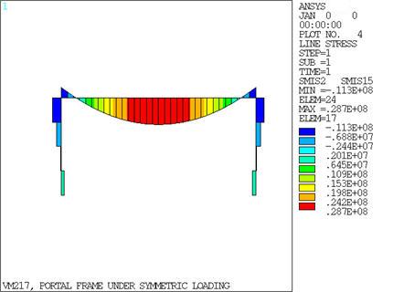
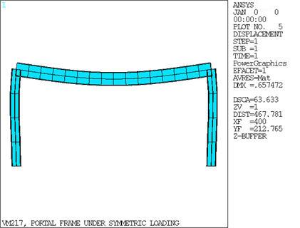
A rigid rectangular frame is subjected to a uniform distributed load ω across the span. Determine the maximum rotation, and maximum bending moment. The moment of inertia for the span, Ispan is five times the moment of inertia for the columns, Icol.

Figure 349: Portal Frame Problem Sketch

Portal Frame Problem Sketch

Material PropertiesLoadingGeometric PropertiesI-Beam Section Data
Ex = 30 x 106 psi
Nuxy = 0.3
ω = -500 lb/in
a = 400 in
L = 800 in
Ispan = 5 Icol
Icol = 20300 in4
W1 = W2 = 16.655 in
W3 = 36.74 in
t1 = t2 = 1.68 in
t3 = 0.945 in

Analysis Assumptions and Modeling Notes

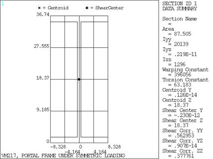
All the members of the frame are modeled using an I-Beam cross section. The cross section for the columns is chosen to be a W36 x 300 I-Beam Section. 
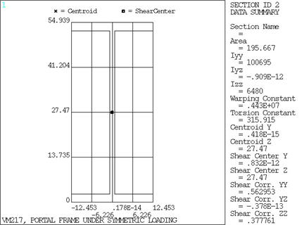
The dimensions used in the horizontal span are scaled by a factor of 1.49535 to produce a moment of inertia that is five times the moment of inertia in the columns. The columns are modeled with BEAM188, while the span is modeled with BEAM189 elements. The theoretical maximum rotation is β =(1/27) (w(a3)/E(Icol)), and the theoretical maximum bend moment is Mmax = (19/54)(w(a2)).

Results Comparison

TargetMechanical APDLRatio
Max. Rotation0.195E-20.213E-21.093
Max. Bend Moment in lb0.281E80.287E81.019

Figure 350: I-Section

I-Section

Figure 351: I-Section Under Symmetric Loading

I-Section Under Symmetric Loading

Figure 352: Moment Diagram

Moment Diagram

Figure 353: Displaced Shape (front view)

Displaced Shape (front view)