VM216

VM216
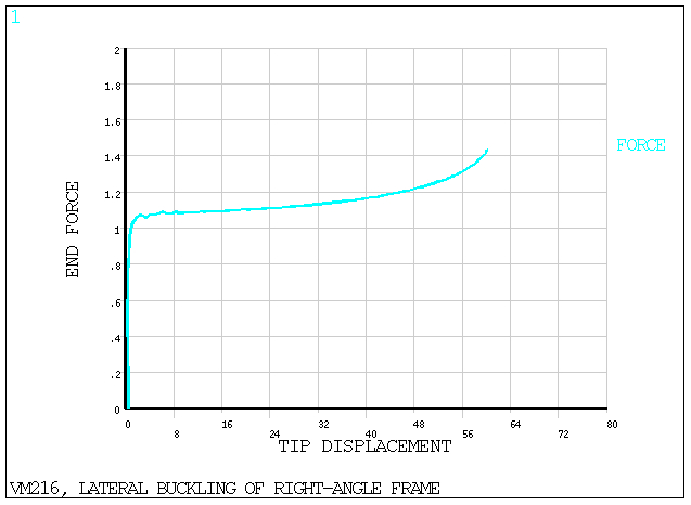
Lateral Buckling of a Right Angle Frame

Overview

Reference:J. C. Simo, L. Vu-Quoc, "Three-Dimensional Finite-Strain Rod Model, Part II", Computer Methods in Applied Mechanical Engineering, Vol. 58, 1986, pp. 79-116.
Analysis Type(s):Static Analysis (ANTYPE = 0)
Element Type(s):
3D Linear Finite Strain Beam Elements (BEAM188)
3D Quadratic Finite Strain Beam Elements (BEAM189)
Input Listing:vm216.dat

Test Case

A 0.6in thick plate that is 30in wide is fashioned into a cantilever right angle frame, and is subjected to an in-plane fixed end load (Fx). The frame is driven to buckling mode by a perturbation load (Fz) applied at the free end, normal to the plane of the frame. This perturbation is removed close to the buckling load. Determine the critical load.

Figure 346: Right Angle Frame Problem Sketch

Right Angle Frame Problem Sketch

Material PropertiesGeometric PropertiesLoading
Ex = 71240 psi
Nuxy = 0.31
lzz = 0.54 in
lyy = 1350 in4
t = 0.6 in
w = 30 in
L = 240 in
Fz = 1 x 10⁻³ lb
Fx = 1.485 lb

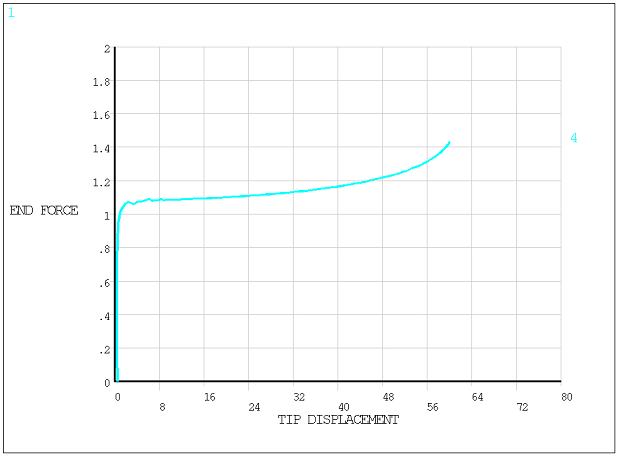
Analysis Assumptions and Modeling Notes

A first analysis is performed using BEAM188 elements. A second analysis is also performed using BEAM189 elements.

Results Comparison

Critical LoadTargetMechanical APDLRatio
BEAM1881.091.0360.951
BEAM1891.091.0360.951

Figure 347: Displacement Tip vs. Applied End Force (Fx) using BEAM188 elements

Displacement Tip vs. Applied End Force (Fx) using BEAM188 elements

Figure 348: Displacement Tip vs. Applied End Force (Fx) using BEAM189 elements

Displacement Tip vs. Applied End Force (Fx) using BEAM189 elements