VM18
VM18
Out-of-Plane Bending of a Curved Bar
Test Case
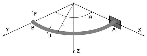
A portion of a horizontal circular ring, built-in at A, is loaded
by a vertical (Z) load F applied at the end B. The ring has a solid
circular cross-section of diameter d. Determine the deflection δ
at end B, the maximum bending stress σBend, and the maximum torsional shear stress τ.
Analysis Assumptions and Modeling Notes
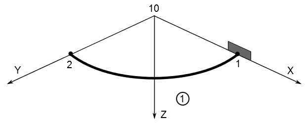
Node 10 is arbitrarily located on the
radius of curvature side of the element to define the plane of the
elbow when PIPE18 elements are used. The
wall thickness is set to half the diameter for a solid bar. Since
the section has no hole in the middle, ovalization cannot occur and PIPE289 elements can be used to determine the deflection
and stresses.
Results Comparison
Corresponds to maximum SAXL at
0° angle location in element solution output.
Corresponds to SXH at 0°
angle location in element solution output.