Format and content for the benchmark test cases are as follows:
Overview--a list of the major reference for the problem, the analysis type, the element type(s), and the name of the test case file (in the printed manual) or a link to the test case file (in the online version).
Test Case--a brief description of the problem and desired solution output. Also included are necessary material properties, geometric properties, loadings, boundary conditions, and parameter definitions. The parameters listed in the parameter definition area are used to define model variables that distinguish each test case run. Each test case is uniquely defined by these parameters and noted in the Results Comparison section.
Representative Mesh Options--a graphics display of a sampling of the finite element meshes created by the test. Parameters defined in the Test Case section are used to specify the finite element mesh patterns shown.
Target Solution--solution used for comparison purposes. The target solution is obtained from the problem reference unless specifically mentioned otherwise in the Assumptions, Modeling Notes, and Solution Comments section.
Results Comparison--results from the Mechanical APDL solution compared with the target solution. Where applicable, the Mechanical APDL results are normalized with respect to the target solution and presented as the ratio of the Mechanical APDL results divided by the target results.
Graphical Results (optional)--results displayed in graphical form.
Assumptions, Modeling Notes, and Solution Comments--general comments on the test case modeling, assumptions, and results interpretation.
In addition to the abbreviations, symbols, and units defined
in Abbreviation and Symbol List, one additional symbol is used
throughout the benchmark studies to identify the location of a target
point where a solution comparison is made. The target point symbol
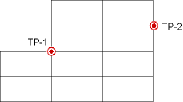
is a bull's-eye: 
Several target points may be used in a test case, so each is
identified separately as Target Pointxx (or TP-XX). The example below
shows two target points on a simple 2D finite element mesh.

Solution comparisons between the target solution and the Mechanical APDL solution at target points are listed in the Results Comparison section.


