


Selecting or creating a cut plane displays a cross-section of the object, which can reveal internal or hidden details.
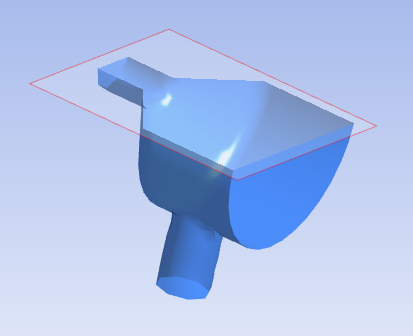
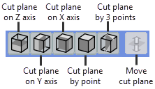
To display a cross-section view, click the Cut plane button ![]() and select one of the three predefined cut planes, or create a custom cut
plane by picking three points on the object's surface. If you are viewing a SpaceClaim
.scdoc file, you can also create a cut plane from a single point. With
the single point method, the cutting plane aligns itself with a selected surface.
and select one of the three predefined cut planes, or create a custom cut
plane by picking three points on the object's surface. If you are viewing a SpaceClaim
.scdoc file, you can also create a cut plane from a single point. With
the single point method, the cutting plane aligns itself with a selected surface.
Note that you can set the view from a particular axis using simple keyboard shortcuts. See Rotating the Model for details.
When you create a cross-section, it applies to the current view only. This makes it possible to have a different cross-section in each view.
When a cross-section view is active, the Move cut plane option  becomes enabled on the Cut plane toolbar. To move a cut plane, simply
click and drag in the direction that you want to move the cut plane. The object view adjusts
as you move the cut plane. To exit this mode, click again to disable it. This returns you to rotation mode.
becomes enabled on the Cut plane toolbar. To move a cut plane, simply
click and drag in the direction that you want to move the cut plane. The object view adjusts
as you move the cut plane. To exit this mode, click again to disable it. This returns you to rotation mode.
To deactivate a cross-section view and return to a full view of the object, click its associated toolbar button to disable it.