


Flextensional transducers usually operate in the low- or mid-frequency range and are attractive because they can generate high-power output. A Class IV type of flextensional transducer, shown in the following figure, contains a stack of piezoelectric ceramics in an elliptically-shaped shell that is covered with rubber to isolate it from the surrounding water:
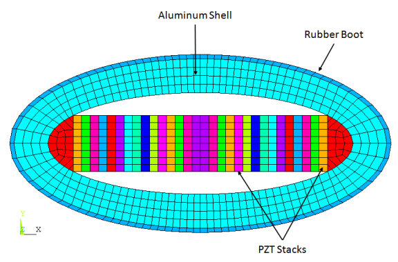
Voltage applied to the piezoelectric ceramics causes motion along the x axis (major axis), which in turn causes amplified motion along the y axis (minor axis). This behavior produces large-volume displacement and therefore high-power output. The Class IV flextensional transducer produces a roughly omnidirectional radiation pattern, although there reduced output occurs along the minor axis.
Transducer design can include changing material properties or dimensions to obtain the desired resonant frequency or response amplitude (quadrupole bending mode).
For this example, the flextensional transducer is idealized as a 2D planar model and excited at 1400 Hz. Results of 2D analyses are compared to a 3D (2.5-D) model. The term 2.5-D describes a single layer of extruded 3D elements used to mimic 2D planar behavior. The example also uses advanced 3D capabilities, such as wave-absorption conditions and far-field postprocessing, to model 2D analyses.