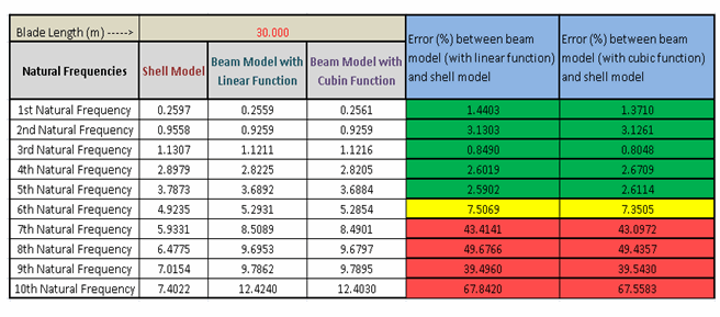
The following table summarizes the natural frequency results from the analyses of the three blade models:

The first five frequencies predicted by the three comparative models are consistent within a range of five percent. The difference increases in higher modes.
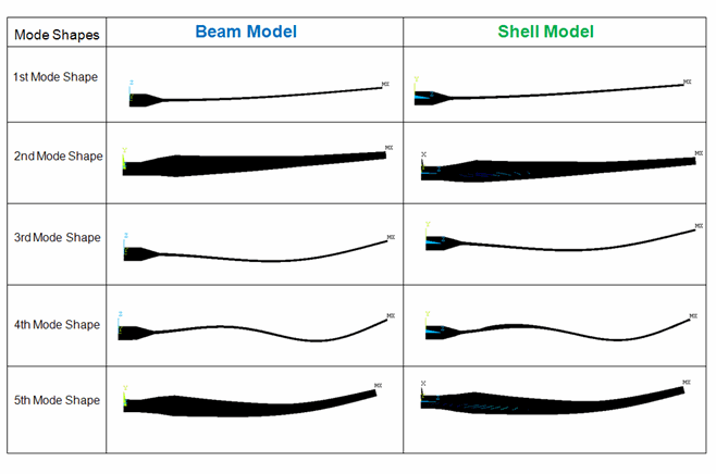
The following figure shows the mode shapes of the first five matching frequencies:
In the SHELL281 reference model, local deformation is evident in higher modes.
The current-technology beams are shown to be effective for simulating slender structures. Compared to 3D modeling using shell and solid elements, beam modeling greatly reduces model-creation time and effort while generally leading to acceptable overall results.
The applicability of current-technology beam elements, however, is bound by the first-order shear-deformation (or Timoshenko) theory. Beam elements are therefore not suitable for extremely stubby structures or structures that may undergo large section deformation (as shown in the higher modes predicted in the SHELL281 model).
With the aid of the mesh (MESH) section subtype, current-technology beam elements can be used for certain types of composite structures. Consider the applicability of beam elements carefully before adopting them for composite-structure simulation. When modeled with beam elements, composite structures introduce these restrictions:
The materials must be oriented in the beam solution coordinate system.
The material properties should not exhibit great variation within the section
Because of beam-theory limitations, some material properties such as Poisson’s ratio, and the coupling between axial stiffness and twisting/transverse shear stiffness, are ignored in beam elements.
The tapered-beam section type (TAPER) can be used with all standard (and even user-defined) beam sections, making it a powerful and flexible tool for modeling structures with complex and varying cross-section geometry.
The cubic interpolation option enables the BEAM188 model to generate an equally accurate solution with far fewer elements than the BEAM188 model with the linear option. Cubic interpolation is also required for modeling partially distributed or pointed loads within the element.
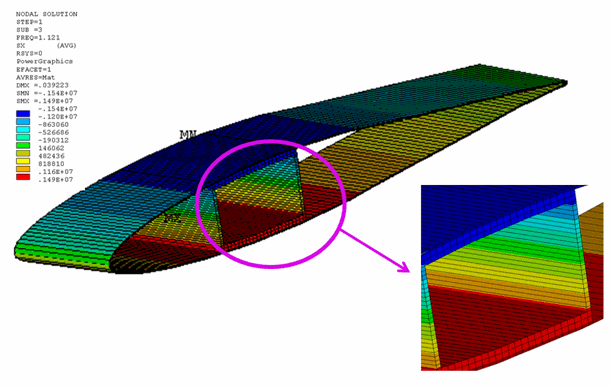
The typical beam-bending stress results (Sxx) with different results-file formats (KEYOPT(15) in current-technology beam and pipe elements) are shown in the following two figures:
Figure 23.10: Averaged Bending-Stress Distribution (Corresponding to Third Mode Shape at Location x = 15m)

With the averaged result format (KEYOPT(15) = 0), continuous bending stress is observed even across the interfaces between two different materials.
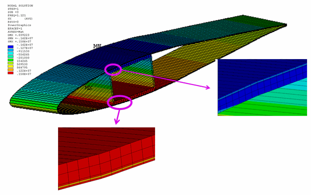
For beams with built-up sections, the nonaveraged format (KEYOPT(15) = 1) is appropriate. As shown in the following figure, the stress discontinuity in heterogeneous media is properly captured using the nonaveraged format:
Figure 23.11: Nonaveraged Bending-Stress Distribution (Corresponding to Third Mode Shape at Location x = 15m)


