The following figure shows the ultrasonic transducer used in this example:
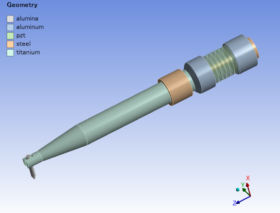
The bonding tool, made of alumina, is shown at the far left. It is connected to the titanium horn by small screws (not modeled). The horn is connected to the piezoelectric driver assembly. The driver assembly consists of piezoelectric rings sandwiched between aluminum front and back plates, which are connected together with a steel bolt that provides prestress. The transducer is mounted to the machine via a steel holder.
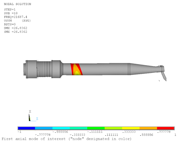
The holder should be placed at the nodal point of the transducer for optimal performance. A modal analysis is performed without the holder, and the first longitudinal mode is determined.
As shown in the following figure, a plot of the z displacement with contour range -1 to 1 provides an idea of the appropriate location to position the holder: