


The 3D model of the transducer is created in Ansys DesignModeler and meshed in Ansys Mechanical, as shown in the following figure:
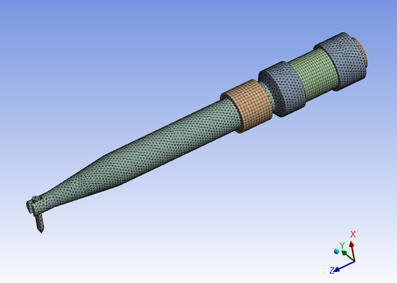
The piezoelectric elements are meshed with SOLID226, and the other parts are meshed with SOLID186 and SOLID187 elements. The total number of elements is 67,756 and the total number of nodes is 115,414.
The coupled-field element SOLID226 supports many physics types. In this case, KEYOPT(1) = 1001 specifies piezoelectric behavior. Piezoelectric elements are orthotropic, so each of the piezoelectric rings assume z-axis polarization with alternating z-axis orientation.
Although copper terminals lie between the piezoelectric rings, they are omitted here for simplicity. Other details and features (such as small screws or wire holes) are also omitted, as they have no effect on the overall response.
The parts are connected via shared nodes along the interfaces. Although contact elements can be used for piezoelectric analyses, they are unnecessary for such a simple geometry in this case.
A bolt connects the top and bottom plates of the driver, as shown in the following figure:
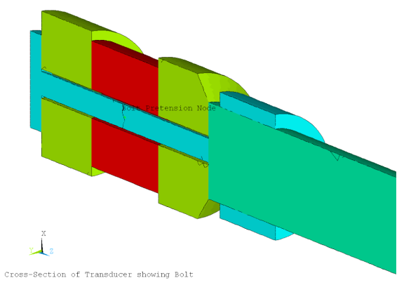
The fastener is split in half with PRETS179 pretension elements connecting the two halves together. The amount of preload or adjustment is controlled via the pretension node.