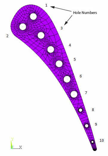
The solid and fluid regions of a parasolid model are already meshed, and the model is read into the database (CDREAD). The solid region is meshed with SOLID70 elements, as shown in this figure:
The fluid region is meshed with FLUID116 line elements. The cross-sectional area of each fluid element is set through a real constant. Appropriate components of nodes and elements have also been created in order to facilitate the application of loads. The components can be viewed if necessary (CMLIST).
SURF152 elements are generated on the inside of the holes (ESURF); however, these surface-effect elements are not coupled to the fluid elements. The following example input couples the SURF152 and FLUID116 elements:
keyop,3,5,2                    ! Allow 2 extra nodes for SURF152 elements for hole # 1
esel,s,type,,13                ! Select Fluid116 elements corresponding to hole # 1
cm,com116,elem                 ! Create a component using the fluid116 elements in each channel
esel,s,type,,3                 ! Select SURF152 elements corresponding to hole# 1
cm,com152,elem                 ! Create a component using the surf152 elements in each channel
allsel                         ! Select all nodes & elements before using MSTOLE
mstole,1,'com152','com116'     ! Map component 'com152' to 'com116' using projection method


