It is common practice in the turbine industry to cool turbine blades with a fluid flowing through cooling holes. As a result of the thermal gradients setup in the blade, thermal stresses are induced which can lead to failure of the blades.
In a typical thermal-stress analysis, temperatures are calculated and then applied as load conditions for the stress analysis. While it is possible to solve for the temperature using a conjugate heat transfer capability of a computational fluid dynamics (CFD) code, it can significant computational resources. A reduced-order model for CFD, assuming a one-dimensional flow through the holes, can provide a relatively inexpensive solution without much loss in accuracy. Typically, the mass flow rates are known through the cooling holes, and certain empirical correlations are used to estimate the film coefficients for heat transfer from the solid to the fluid.
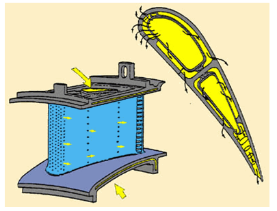
Because of the proprietary nature of these types of analyses, it was not possible to obtain a realistic model and loading conditions for this analysis from industry sources. A simplified model described in a NASA report is used instead, and an understanding that turbine blade cooling passages and loading conditions are much more complex in realistic models is assumed. For example, the following figure illustrates that the cooling passages in an actual turbine blade (shown in yellow) can join or branch with each other inside the blade, and the coolant is allowed to bleed through the cooling holes and cool the external surface of the blade:
In this problem, however, the cooling holes do not interact with each other and the coolant is confined to the interior of the blade.
For further information, see the following resources:
SURF152 and FLUID116 documentation in the Element Reference.
SURF152 - 3D Thermal Surface Effect and FLUID116 - Coupled Thermal-Fluid Pipe in the Mechanical APDL Theory Reference.


