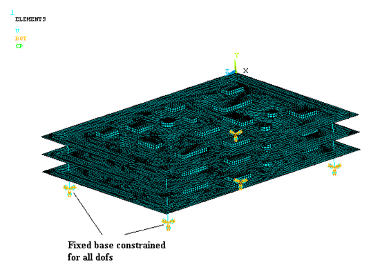
The boards of the PCB assembly are connected with five supporting columns. The base of the columns (y = -60) are constrained on all degrees of freedom as shown in the figure below:
The following example input shows how the fixed constraints are applied:
CM, N_BASE_EXCITE, NODE           ! Group the set of nodes at the base of the columns as a component
D, ALL, ALL                       ! Apply displacement and rotation constraints to this set
N_BASE_EXCITE in the input above specifies the nodes at the junction of the supporting columns with the base. For PSD analysis, the loading is applied in the form of base excitation on the set N_BASE_EXCITE.
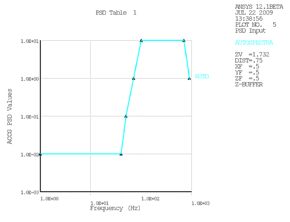
The PSD values for the input spectrum at different frequency points are shown in the figure below. The input segment between 1.0E-02 and 1.0E+01 has 2 intermediate points in order to obtain a good fit for the curve-fitting polynomial used in the PSD integration process.
The following example input shows how base excitation is applied:
/SOLU
ANTYPE, SPECTR                                         ! Perform a spectral analysis
SPOPT, PSD                                             ! Use power spectral density (PSD) as the spectrum
                                                       ! type
PSDUNIT, 1, ACCG, 9.81*1000                            ! Use input table 1 with acceleration spectrum in
                                                       ! terms of acceleration due to gravity
PSDFRQ, 1, , 1, 40, 50, 70.71678, 100, 700, 900, 1E3   ! Define the frequency points in the input table 1
PSDVAL, 1, 0.01, 0.01, 0.1, 1, 10, 10, 1, 1            ! Define the PSD values in the input table 1
PSDGRAPH, 1                                            ! Display the input PSD curve from table 1
DMPRAT, 0.05                                           ! Set the damping ratio as 5%
D, N_BASE_EXCITE, UY, 1                                ! Apply base excitation on the set of nodes
                                                       ! N_BASE_EXCITE in the y direction from table 1


